202duino で シリアル通信 [Arduino]
202duinoでCH340Eの機能をUPDI書き込みだけでなく、シリアル通信にも使用したサンプル。
1. ジャンパを取り付ける(UPDI書き込みモード)
2. 以下のサンプルスケッチを書き込む
3. ジャンパを外す(付けたままだとTx,Rxが接続状態になる)
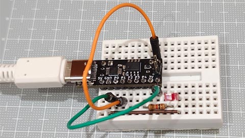
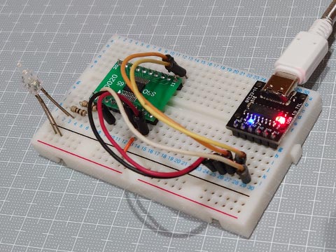
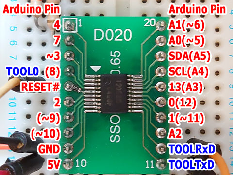
4. ブレッドボードの配線
・Rx(CH340E) と Arduino 0番(ATtiny202:PA6, TXD)をつなぐ
・Tx(CH340E) と Arduino 1番(ATtiny202:PA7, RXD)をつなぐ
・確認用LED を Arduino 4番(LED_BUILTIN)とつなぐ
5. シリアルモニタで動作確認
void setup() {
        Serial.begin(9600);
        pinMode(LED_BUILTIN, OUTPUT);
}

void loop() {
        while( Serial.available() ) {
                Serial.print("I received : ");
                Serial.println( Serial.read(), DEC);
                digitalWrite(LED_BUILTIN, HIGH);
                delay(200);
                digitalWrite(LED_BUILTIN, LOW );
                delay(200);
        }
        Serial.println("I'm waiting.");
        delay(1000);
}
「最大2048バイトのフラッシュメモリのうち、スケッチが1864バイト(91%)を使っています。」
ほぼ他の事できないけど、、。
202duino で Charlieplexing [Arduino]
事前に環境設定でボードマネージャの追加などしておきます。
megaTinyCore_Installation.md at master · SpenceKonde_megaTinyCore · GitHub
https://github.com/SpenceKonde/megaTinyCore/blob/master/Installation.md
The boards manager URL is:
作成した 202duino 、、ちゃんと5ピン全ピン使用できるか、LEDのCharlieplexingで確認してみました。
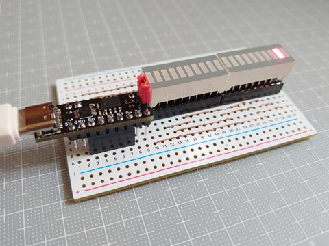
10連LEDを2個使って、20個のLEDを操作。
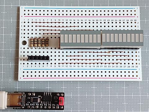
表は一見きれい。
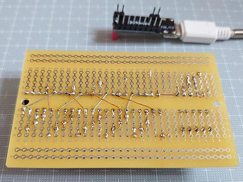
裏はきたない。ぼくの嫌いなエナメル線を使用。
<202duino専用スケッチ>
AVR 0シリーズの直接ポート操作もしてみた。
megaTinyCore_Ref_DirectPortManipulation.md at master · SpenceKonde_megaTinyCore · GitHub
https://github.com/SpenceKonde/megaTinyCore/blob/master/megaavr/extras/Ref_DirectPortManipulation.md
レジスタはいじらない代わりに、操作ピン数、操作ピン番号、LED数を指定するだけでいい汎用スケッチも作ってみた。4ピン 10LEDのやつでも確認済。
<汎用スケッチ>
megaTinyCore_Installation.md at master · SpenceKonde_megaTinyCore · GitHub
https://github.com/SpenceKonde/megaTinyCore/blob/master/Installation.md
The boards manager URL is:
http://drazzy.com/package_drazzy.com_index.json
作成した 202duino 、、ちゃんと5ピン全ピン使用できるか、LEDのCharlieplexingで確認してみました。
10連LEDを2個使って、20個のLEDを操作。
表は一見きれい。
裏はきたない。ぼくの嫌いなエナメル線を使用。
<202duino専用スケッチ>
// Drive 20 LEDs with 5 pins
const uint8_t PoK[20] = {  0,0,0,0,1,1,1,1,2,2,  2,2,3,3,3,3,4,4,4,4  };    // Pin of Cathode(K) (-)
//                       +---------------------+---------------------+
//                       | | | | | | | | | | | | | | | | | | | | | | |
//                       | _ _ _ _ _ _ _ _ _ _ | _ _ _ _ _ _ _ _ _ _ | Cathode(K)
//                       | ^ ^ ^ ^ ^ ^ ^ ^ ^ ^ | ^ ^ ^ ^ ^ ^ ^ ^ ^ ^ | Anode(A)
//                       | | | | | | | | | | | | | | | | | | | | | | |
//                       +---------------------+---------------------+
const uint8_t PoA[20] = {  1,2,3,4,0,2,3,4,0,1,  3,4,0,1,2,4,0,1,2,3  };    // Pin of Anode(A)   (+)
const uint8_t P2PA[5] = { PIN6_bm, PIN7_bm, PIN1_bm, PIN2_bm, PIN3_bm };    // Pin to PORTA

void setup() {
}

void loop() {
static uint8_t pos = 0, dir = true;         // Position and Direction(0:-, 1:+) of light
  lightUpPA( dir ? pos++ : pos-- );
  delay(50);
  if(pos == 19 || pos == 0) dir = 1 ^ dir;  // change direction when the light reach the edge
}

void lightUpPA(uint8_t n){                  // PORTA form
  for(uint8_t i=0; i<5; i++) {
    if     ( PoA[n]==i ) PORTA.DIRSET = PORTA.OUTSET = P2PA[i];     // set anode HIGH
    else if( PoK[n]==i ) PORTA.DIRSET = PORTA.OUTCLR = P2PA[i];     // set cathode LOW
    else                 PORTA.DIRCLR = P2PA[i];                    // set to Hi-Z (input)
  }
}
AVR 0シリーズの直接ポート操作もしてみた。
megaTinyCore_Ref_DirectPortManipulation.md at master · SpenceKonde_megaTinyCore · GitHub
https://github.com/SpenceKonde/megaTinyCore/blob/master/megaavr/extras/Ref_DirectPortManipulation.md
レジスタはいじらない代わりに、操作ピン数、操作ピン番号、LED数を指定するだけでいい汎用スケッチも作ってみた。4ピン 10LEDのやつでも確認済。
<汎用スケッチ>
// Drive N*(N-1) LEDs with N pins
#define NoL       20                                // number of LEDs
#define NoP       5                                 // number of pins
const uint8_t     P2INO[NoP]= { 0, 1, 2, 3, 4 };    // LED Pin to Arduino pin
#define PoK(n)  ((n)/((NoP)-1))                     // LED Pin of Cathode(K) (-)
#define PoA(n)  ((1+(n)*((NoP)+1)/(NoP))%(NoP))     // LED Pin of Anode(A)   (+)

void setup() {
}

void loop() {
  static uint8_t pos = 0, dir = true;       // Position and Direction(0:-, 1:+) of light
  lightUp( dir ? pos++ : pos-- );
  delay(100);
  if(pos == (min(NoL, (NoP)*((NoP)-1))-1) || pos == 0) dir = 1 ^ dir;   // change direction when the light reach the edge
}

void lightUp(uint8_t n){
  for(uint8_t i=0; i<NoP; i++) {
    if( PoA(n)==i || PoK(n)==i ) {          // If the pin is connected to the anode or cathode of the LED,
      pinMode( P2INO[i], OUTPUT );          //   set to output pin
      digitalWrite( P2INO[i], PoA(n)==i );  //   set cathode LOW, set anode HIGH
    } else {
      pinMode( P2INO[i], INPUT  );          // Set to Hi-Z
    }
  }
}
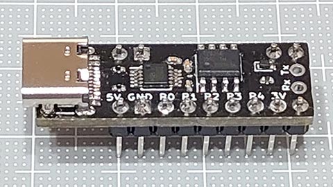
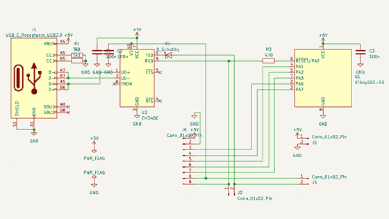
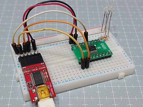
202duino (ATtiny202 + CH340E + type-C) なるものを作ってみた。 [Arduino]
202duino (ATtiny202 + CH340E + type-C)なるものを作ってみました。
<コンセプト>
・ATtiny202等の新シリーズの8ピンAVRをブレッドボードで使いたい
・とにかくコンパクトなのがいい
・すべての信号ピンは一列で
(ICピンの並び順ではなく、megaTinyCoreでのピン番号の順で)
・USB type-Cで「電源」と「UPDI」と「シリアル通信」を使いたい
・できれば片面基板で
megaTinyCore_ATtiny_x02.md at master · SpenceKonde_megaTinyCore · GitHub
https://github.com/SpenceKonde/megaTinyCore/blob/master/megaavr/extras/ATtiny_x02.md
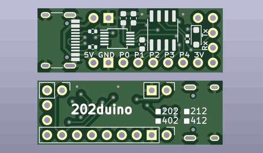
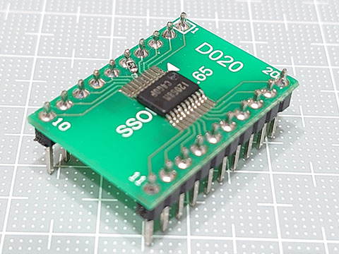
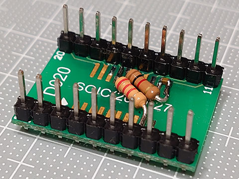
<工夫した構造>
・300mil幅に収める
・信号ピンは一列、電源は左右対称に同一のもの、シリアル通信は左右別
・シリアル-UPDIの部分を完全につながず一部ジャンパにした
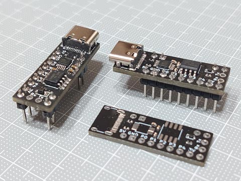
これにより
・DIP状のため安定してブレッドボードに固定できる
・ブレッドボードの片側半分だけでも配置ができる
このときは、Tx, Rxが接続されUPDI書き込みが可能となる
・逆にブレッドボードの中央をまたぐ場合は、、
Tx, Rxを接続しないことにより、UPDIでの書き込み不可(ライトプロテクト)となる
ジャンパピンを立ててジャンパプラグをショートすればUPDI書き込み可になる
Tx, Rxをシリアル通信用に使うこともできる
<あとがき>
当初、ショットキーバリアダイオードをSOD-523で基板を作っていたものの、SOD-523のダイオードがなかなか入手できず、SOD-323(+キャパシタも0406(1005M)→0603(1608M))用の基板を注文したら、後者の基板が届く前にSOD-523が届いてしまったため2バージョンできてしまった。
このくらいのSMD部品までなら、きれいな実装を目指さなければなんとかなる、、でもきれいに載せたい(ので難しい)。
ポリスイッチ、逆流防止ダイオードなどの安全系パーツは使用していないので気をつけよう。
フラックスの除去用に歯ブラシがあったらいいのかな。
<コンセプト>
・ATtiny202等の新シリーズの8ピンAVRをブレッドボードで使いたい
・とにかくコンパクトなのがいい
・すべての信号ピンは一列で
(ICピンの並び順ではなく、megaTinyCoreでのピン番号の順で)
・USB type-Cで「電源」と「UPDI」と「シリアル通信」を使いたい
・できれば片面基板で
megaTinyCore_ATtiny_x02.md at master · SpenceKonde_megaTinyCore · GitHub
https://github.com/SpenceKonde/megaTinyCore/blob/master/megaavr/extras/ATtiny_x02.md
<工夫した構造>
・300mil幅に収める
・信号ピンは一列、電源は左右対称に同一のもの、シリアル通信は左右別
・シリアル-UPDIの部分を完全につながず一部ジャンパにした
これにより
・DIP状のため安定してブレッドボードに固定できる
・ブレッドボードの片側半分だけでも配置ができる
このときは、Tx, Rxが接続されUPDI書き込みが可能となる
・逆にブレッドボードの中央をまたぐ場合は、、
Tx, Rxを接続しないことにより、UPDIでの書き込み不可(ライトプロテクト)となる
ジャンパピンを立ててジャンパプラグをショートすればUPDI書き込み可になる
Tx, Rxをシリアル通信用に使うこともできる
<あとがき>
当初、ショットキーバリアダイオードをSOD-523で基板を作っていたものの、SOD-523のダイオードがなかなか入手できず、SOD-323(+キャパシタも0406(1005M)→0603(1608M))用の基板を注文したら、後者の基板が届く前にSOD-523が届いてしまったため2バージョンできてしまった。
このくらいのSMD部品までなら、きれいな実装を目指さなければなんとかなる、、でもきれいに載せたい(ので難しい)。
ポリスイッチ、逆流防止ダイオードなどの安全系パーツは使用していないので気をつけよう。
フラックスの除去用に歯ブラシがあったらいいのかな。
RL78/G15 FPB と USBシリアル変換モジュール [Arduino]
自作 RL78/G15 Fast Prototyping Board のUSBインターフェイスに、これまで一番差し障りのないFTDI FT232 シリーズでやっていましたが、他のものはどうでしょう?
DTR#が出ていればよさそうなので、CH340Cが載ったやつで試してみました。
結果はOKでした。
USB type-Cで気持ちいい。
さらに、書き込みに30秒かかっていたのが、5秒もかからなくなりました。
本家より優秀になっている。
<追加報告>
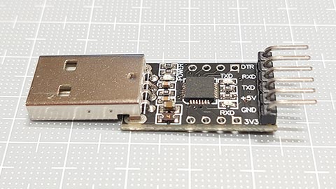
CP2102のUSBシリアル変換モジュールが出てきたので試してみたら、こちらはダメでした。
DTR#が出ていればよさそうなので、CH340Cが載ったやつで試してみました。
結果はOKでした。
USB type-Cで気持ちいい。
さらに、書き込みに30秒かかっていたのが、5秒もかからなくなりました。
本家より優秀になっている。
<追加報告>
CP2102のUSBシリアル変換モジュールが出てきたので試してみたら、こちらはダメでした。
RL78/G15 FPB の tone()関数で和音 [Arduino]
RL78/G15 のレジスタを直接いじるの大変そう。PWM作るのにもe2stdioとかいうのを使ってやるみたい。
そこでtone()関数をみてみると、、
RL78G15 20ピン Fast Prototyping Board ピンリスト · renesas_Arduino Wiki · GitHub
https://github.com/renesas/Arduino/wiki/RL78G15-20%E3%83%94%E3%83%B3-Fast-Prototyping-Board-%E3%83%94%E3%83%B3%E3%83%AA%E3%82%B9%E3%83%88
2-7. Tone のところで、Tone output pinに指定できるのは、Arduino 0番, 3番, 13番の3つ。
3つ同時に使えるかと思ったら、3番, 13番を同時に使うのはダメで2和音まででした。
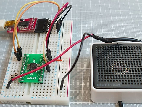
第5オクターブで曲データを作っています。
これより低い音はうまく出せないみたい。
楽譜データの音符などは、notes2.h で。
Digisparkで音楽演奏【楽譜編】
https://hello-world.blog.ss-blog.jp/2022-07-04
そこでtone()関数をみてみると、、
RL78G15 20ピン Fast Prototyping Board ピンリスト · renesas_Arduino Wiki · GitHub
https://github.com/renesas/Arduino/wiki/RL78G15-20%E3%83%94%E3%83%B3-Fast-Prototyping-Board-%E3%83%94%E3%83%B3%E3%83%AA%E3%82%B9%E3%83%88
2-7. Tone のところで、Tone output pinに指定できるのは、Arduino 0番, 3番, 13番の3つ。
3つ同時に使えるかと思ったら、3番, 13番を同時に使うのはダメで2和音まででした。
// RL78/G15 FPB tone function test
#include "notes2.h"                         // Definition data of notes ( pitch (scale & octave), and note value (length))
#define MAX_TRACK   2                       // Maximum number of tracks
const uint8_t  ToneOutputPin[] = { 0, 13 }; // two of 0,3,13 pins (No combination of 3 and 13)
const uint16_t F_SCALE[] = { 33488, 35479, 37589, 39824, 42192, 44701, 47359, 50175, 53159, 56320, 59669, 63217 };
                                            // basic frequency of 12-note scale (from C11 to B11)(Hz)
const uint16_t Frogs[] = {                  // melody data
  120 ,   0 ,
  c5q , d5q , e5q , f5q , e5q , d5q , c5q , RSq , e5q , f5q , g5q , a5q , g5q , f5q , e5q , RSq ,
  c5q , RSq , c5q , RSq , c5q , RSq , c5q , RSq , c5e , c5e , d5e , d5e , e5e , e5e , f5e , f5e ,
  e5q , d5q , c5q , RSq , RSd , RSd ,   0 ,
  RSd ,
  c5q , d5q , e5q , f5q , e5q , d5q , c5q , RSq , e5q , f5q , g5q , a5q , g5q , f5q , e5q , RSq ,
  c5q , RSq , c5q , RSq , c5q , RSq , c5q , RSq , c5e , c5e , d5e , d5e , e5e , e5e , f5e , f5e ,
  e5q , d5q , c5q , RSq , RSd ,   0 ,   0 };

void setup(){
}

void loop(){
  const uint16_t *d = Frogs;                // Pointer of melody data
  const uint16_t *p[MAX_TRACK];             // Pointer for each track of the score
  uint8_t  Tracks, t;                       // Number of tracks and counter
  uint16_t note;                            // Note (pitch + note value) information
  uint8_t  len[MAX_TRACK] = {};             // Length of note (how many 96th notes) (subtraction counter)
  uint32_t usInt, usExp;                    // sound division interval, sound expire time(usec)
  usInt = 1000000*60*4 / MIN_NOTE / *d++;   // Calculate standard 96th note length(usec) from tempo
  for( Tracks=0; Tracks<MAX_TRACK; ) {      // Get the number of tracks and the start position of each track from the song data
    if( *d++ != 0 ) continue;               // Skip until the break comes
    if( *d   == 0 ) break;                  // If two zeros follow, end of data
    p[ Tracks++ ] = d;                      // Get location in memory, Count up the number of tracks
  }
  usExp = micros();
  do {                                      // Processing of score for each reference note(96th note) length
    for( t=0; t<Tracks; t++) {
      if( !len[t]-- ) {                     // Subtract the length of the note, and when it reaches 0, go to the next note
        if( !(note = *p[t]++) ) return;     // end if note = 0
        len[t]  = (note & 0x00ff) - 1;      // The lower 8 bits are the length of the note (how many times the length of a 96th note)
        if(note & 0xff00)                   // note(16bit) : Upper 4 bits are octave, next 4 bits are pitch class (0-11)
                tone( ToneOutputPin[t], F_SCALE[(note>>8)&0x0f] >> (11-(note>>12)), 0 );
        else  noTone( ToneOutputPin[t] );   // 0 for rests
      }
    }
    usExp += usInt;
    while( micros() < usExp );              // wait until expiration
  } while( note );
  for( t=0; t<Tracks; t++) noTone( ToneOutputPin[t] );  // stop all sounds
  delay(1000);
}
第5オクターブで曲データを作っています。
これより低い音はうまく出せないみたい。
楽譜データの音符などは、notes2.h で。
Digisparkで音楽演奏【楽譜編】
https://hello-world.blog.ss-blog.jp/2022-07-04
タグ:RL78/G15
RL78/G15 FPB 自作してみた。 [Arduino]
こんな感じで、RL78/G15をDIP化およびシリアル書き込み周辺の抵抗などを載せ、Arduino Pro Miniなどで使うUSBシリアル変換アダプタを使用してスケッチを書き込むことができました。
(秋月電子通商のAE-UM232Rでも行けました。)
シリアルポートを使用した RL78 デバッグ機能
https://www.renesas.com/jp/ja/document/apn/rl78-debugging-functions-using-serial-port-application-note
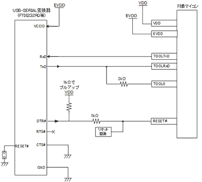
できるだけジャンプワイヤーを使用しなくていいように、DIP化基板に抵抗などを載せました。
RL78/G15(R5F12068MSP)の5番(RESET#)のラインを切断し、チップ抵抗 1kΩを挟む。
裏面は、電源部にキャパシタ。他、1kΩ、2kΩ(がなかったので2.2kΩ)を接続しました。
PDFには、DTRがない場合はRTSも使えるけど「RTSを使う場合は必ずプロパティの設定変更を行ってください。」とのこと。
他、Arduino IDEのシリアルモニタ等を使う場合は、「74LVC1G126」というパーツが必要らしい。RL78/G15 FPBにも載っている。
Arduino上でのピン番号とのIC上のピンとの対応
Lチカ サンプル
タグ:RL78/G15
RL78/G15 Fast Prototyping Board 買ってみた。 [Arduino]
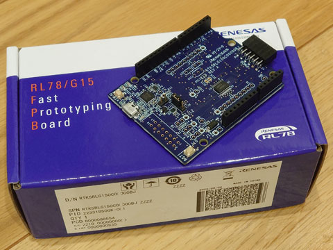
Renesas RL78/G15 を使った Arduinoっぽいボードを発見したので購入しました。
マルツで売ってました。
<参考URL>
RTK5RLG150C00000BJ - RL78/G15 Fast Prototyping Board | Renesas
https://www.renesas.com/jp/ja/products/microcontrollers-microprocessors/rl78-low-power-8-16-bit-mcus/rtk5rlg150c00000bj-rl78g15-fast-prototyping-board
RL78/G15 FAST PROTOTYPING BOARD RTK5RLG150C00000BJ ルネサスエレクトロニクス(Intersil・IDT)製|電子部品・半導体通販のマルツ
https://www.marutsu.co.jp/pc/i/43306583/
ホーム · renesas/Arduino Wiki · GitHub
https://github.com/renesas/Arduino/wiki/%E3%83%9B%E3%83%BC%E3%83%A0
ボードマネージャファイル
・RL78/G15-20p Fast Prototyping Board
https://raw.githubusercontent.com/renesas/Arduino/master/hardware/package_index_rl78g15_fpb_p20_bundled.json
<とりあえずサンプル>
スケッチ例あるBlinkはそのままではうごきませんでした。
#define LED_BUILTIN 24
となっているようです。
ボード上に2つLEDがついていて、LED1がArduino上のデジタル7番(IC 2番ピン, P20)で、LED2がArduino上のデジタル4番(IC 1番ピン, P21)となっていました。
#define  LED1_BUILTIN  7
#define  LED2_BUILTIN  4
void setup() {
  pinMode(LED1_BUILTIN, OUTPUT);
  pinMode(LED2_BUILTIN, OUTPUT);
}

void loop() {
  digitalWrite(LED1_BUILTIN, HIGH);
  digitalWrite(LED2_BUILTIN, LOW);
  delay(500);
  digitalWrite(LED1_BUILTIN, LOW);
  digitalWrite(LED2_BUILTIN, HIGH);
  delay(500);
}
このスケッチ書き込みに30秒くらいかかる。なんでだろう。
タグ:RL78/G15
三菱エアコン 無線LANアダプター「MAC-900IF」を取り付ける [作業]
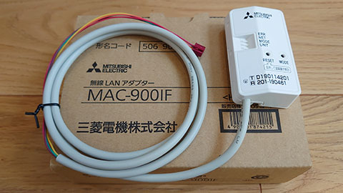
今年(2023年)のお正月に購入したエアコン用の無線LANアダプター「MAC-900IF」をやっと取り付けてみた。
ちょうどエアコン使わない時期なので、エアコンの掃除がてら、、。
MAC-900IF|三菱電機WIN2K
https://www.mitsubishielectric.co.jp/ldg/wink/ssl/displayProduct.do?pid=310070
取り付け対象は「霧ヶ峰 MSZ-ZXV6319S-W」。
検索すると同様のアダプター取り付けの公式・非公式の解説ページや動画があり、何番煎じかわかりませんが載せてみます。
対応アダプター取付_エアコンMSZ-Z_3_無線LANアダプターの取付け - YouTube
https://www.youtube.com/watch?v=GMY2Z26zyVI
★電源プラグを外す
★ムーブアイのカバーを外す
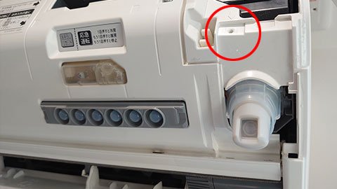
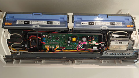
★前面パネルを外す
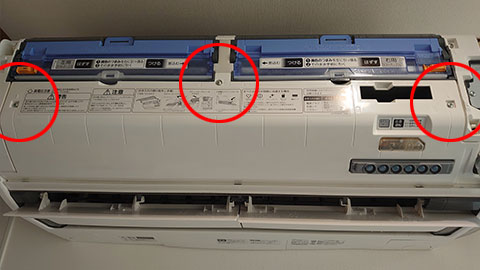
★金属パネルを外す

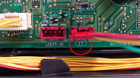
★無線LANアダプターのコネクタを接続
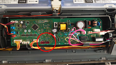
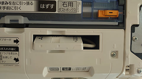
★ケーブルの取りまわし
動画では表示・ムーブアイのパーツを完全にはずしていたけど、すこし爪をはずして隙間をつくって押し込んだ。
★元に戻して完成
あとはスマホ、無線LANルータなどの設定して終了。
 MAC-900IF")
三菱電機 無線LANアダプター(スマートフォン・スマートスピーカー・HEMS用) MAC-900IF
- 出版社/メーカー: 三菱電機
- メディア:
タグ:Wi-Fi


