UNO R4 で WAVファイルを再生する [Arduino]
UNOでDACが使えることが分かったので、これを使って音声を再生してみました。
ファイル形式は、モノラル 8ビットのシンプルなwavファイルのみ。
<音源の準備>
・google翻訳の音声をmp3ファイルに変換してくれるサイトからゲット。
・これを Audacity を使って、モノラルの unsigned 8bit のwavファイルに変換。
・PROGMEM作蔵さん でC言語の配列に変換。(PROGMEMでなくてもいい)
バイナリファイルをC言語のデータ配列に変換する:放課後マイコンクラブ:SSブログ
https://hello-world.blog.ss-blog.jp/2016-10-16
スケッチは以下のとおりです。
レジスタ操作なしの純粋なArduinoスケッチで仕上げました。
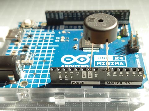
AVRと違いピンのドライブ能力が高くないようで、直接スピーカーをつなげてもうまく音がでませんでした。
圧電サウンダだとかなり小さい音ですが、きれいに聞こえました。
音声データはこんな感じ(略しています)
ファイル形式は、モノラル 8ビットのシンプルなwavファイルのみ。
<音源の準備>
・google翻訳の音声をmp3ファイルに変換してくれるサイトからゲット。
・これを Audacity を使って、モノラルの unsigned 8bit のwavファイルに変換。
・PROGMEM作蔵さん でC言語の配列に変換。(PROGMEMでなくてもいい)
バイナリファイルをC言語のデータ配列に変換する:放課後マイコンクラブ:SSブログ
https://hello-world.blog.ss-blog.jp/2016-10-16
スケッチは以下のとおりです。
レジスタ操作なしの純粋なArduinoスケッチで仕上げました。
AVRと違いピンのドライブ能力が高くないようで、直接スピーカーをつなげてもうまく音がでませんでした。
圧電サウンダだとかなり小さい音ですが、きれいに聞こえました。
#include "hw8k.h"                               // wave file data

void setup() {
  analogWriteResolution(8);
}

void loop() {
  playWav( hw8k_en );
  delay(500);
  playWav( hw8k_ja );
  delay(500);
}

void playWav( const uint8_t d[] ) {             // monoral 8bit only
  uint32_t i, rate, len, usInt, usExp;
  rate  = *(uint32_t*)(&d[ 0x18 ]);             // Sampling rate
  len   = *(uint32_t*)(&d[ 0x28 ]);             // Data size
  usInt = 1000000 / rate;                       // Time interval
  usExp = micros();
  for( i = 0x2c; i < len; i++ ) {
      analogWrite( DAC, d[ i ] );
      while( micros() - usExp < usInt );
      usExp = micros();
  }
}
音声データはこんな感じ(略しています)
const uint8_t hw8k_ja[] = {    // file size : 13100 bytes
  0x52,0x49,0x46,0x46,0x24,0x33,0x00,0x00,0x57,0x41,0x56,0x45,0x66,0x6d,0x74,0x20,
  0x10,0x00,0x00,0x00,0x01,0x00,0x01,0x00,0x40,0x1f,0x00,0x00,0x40,0x1f,0x00,0x00,
  0x01,0x00,0x08,0x00,0x64,0x61,0x74,0x61,0x00,0x33,0x00,0x00,0x80,0x7f,0x80,0x80,
  0x7f,0x80,0x7f,0x80,0x7f,0x80,0x7f,0x80,0x7f,0x80,0x7f,0x80,0x7f,0x80,0x7f,0x80,
        ......
  0x7f,0x80,0x80,0x7f,0x80,0x7f,0x80,0x7f,0x80,0x80,0x80,0x7f
};

const uint8_t hw8k_en[] = {    // file size : 10220 bytes
  0x52,0x49,0x46,0x46,0xe4,0x27,0x00,0x00,0x57,0x41,0x56,0x45,0x66,0x6d,0x74,0x20,
  0x10,0x00,0x00,0x00,0x01,0x00,0x01,0x00,0x40,0x1f,0x00,0x00,0x40,0x1f,0x00,0x00,
  0x01,0x00,0x08,0x00,0x64,0x61,0x74,0x61,0xc0,0x27,0x00,0x00,0x80,0x80,0x80,0x80,
  0x80,0x80,0x80,0x80,0x80,0x80,0x80,0x80,0x80,0x80,0x80,0x80,0x80,0x80,0x80,0x7f,
        ......
  0x7f,0x80,0x80,0x80,0x7f,0x80,0x7f,0x80,0x7f,0x80,0x7f,0x80
};
UNO R4 の DAC について調べてみた。 [Arduino]
Arduino UNO R4 には、DAC (Digital Analog Converter) がついています。
アナログのA0ピンです。
デジタルでいうと14ピン。
UNO R4だと、定数で DAC および A0 が 14 となっていました。
どうやって出力するかというと、analogWrite を使うだけ。
analogWrite( ピン番号 , 値 );
でいい。
値は、
analogWriteResolution( 分解能(ビット数)) ;
で指定した範囲。
これを指定しない場合はデフォルトの8になるので、0-255の範囲。12を指定すると0-4095の範囲。
// UNO R4 DAC analogWrite

void setup() {
  analogWriteResolution( 12 );  // If not specified, the default is 8.
}

void loop() {
  static uint16_t val;
  val = ++val & 0x0fff;         // 0, 1, 2, ..., 4095 , 0, 1, 2, ...
  analogWrite( DAC, val );
  delayMicroseconds( 500 );
}
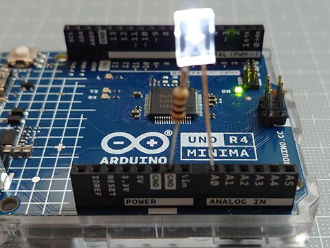
ピン番号がDAC対応ピン(DAC/A0/D14)だとDACで出力し、非対応ピンの場合にはPWMで出力するようになっています。13番ピン(LED_BUILTIN)にすると、PWMで内臓LEDが光ります。
DACピンでの analogWrite() は呼び出されると、大まかに以下の手順。
1. ピンがDAC使用可能ピンか確認
2. DACのチャンネル取得?
3. dac.cppのanalogWriteに値を渡す
4. 値を分解能に合わせてスケーリング
5. 値を書き込む
という手順です。
%localAppData%\Arduino15\packages\arduino\hardware\renesas_uno\1.0.4\cores\arduino
(1.0.4のところはバージョンによって異なります。)
ここの dac.cpp や analog.cpp を参照。
1, 2の作業を毎回ではなく、先にしておいて、3~5だけを行うのが以下のスケッチ。
少し早くなります。(delayMicroseconds()をなくすとよくわかります。)
// UNO R4 DAC analogWrite (faster)

#include <dac.h>

static CDac dac( A0 );

void setup() {
  analogWriteResolution( 12 );  // If not specified, the default is 8.
}

void loop() {
  static uint16_t val;
  val = ++val & 0x0fff;         // 12bit : 0, 1, 2, ..., 4095 , 0, 1, 2, ...
  dac.analogWrite( val );       // faster
  delayMicroseconds( 500 );
}
これでいいのかどうかはわからないけど、とりあえず動いている。
analogWrite()のかわりに、init()とset()だけでいけると思ったけど、だめだった。
さらに、レジスタをいじってみる。(5の作業のみ。)
// UNO R4 DAC analogWrite (fastest)

void setup() {
  analogWriteResolution( 12 );  // If not specified, the default is 8.
  analogWrite( DAC, 0 );        // For initialization.
}

void loop() {
  static uint16_t val;
  val = ++val & 0x0fff;         // 12bit : 0, 1, 2, ... , 4095, 0, 1, 2, ...
  R_DAC->DADR[0] = val;
  delayMicroseconds( 500 );
}
DACの初期設定もレジスタをいじるのは大変なので、analogWrite( DAC, 0 ); を1回呼び出すことで代用。
処理速度は断然速いです。
(delayMicroseconds()を外して書き込み、UNO R4を振ると残像の細かさがダントツです。)
(LEDの明るさで動作確認をしたけど、LEDは一定の電圧以下では光らないので、LEDの明るさ調整にはPWMのほうが向いていそう。)
CH552 で リモコン信号をシリアル送信 [Arduino]
CH552にも移植してみました。
Ch55xduinoで注意が必要なのは、、
・C++ではなくCである
・pulseIn()がない
・シリアル通信がいつものと異なる
pulseIn()については、100μ秒オーダー程度の精度で十分なので、micros()で自作。
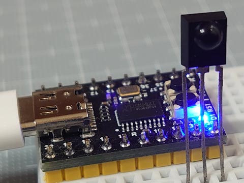
ちなみに、CH552 のピン P1.0~P1.7, P3.0~P3.7 のうち、CH552 mini coreでは、P1.2, P1.3 は外部クリスタル、P3.6, P3.7 はそれぞれUDP, UDMで、USBとつながっているためI/Oピンには使えません。
ちょっとこれで嵌りました。
Ch55xduinoで注意が必要なのは、、
・C++ではなくCである
・pulseIn()がない
・シリアル通信がいつものと異なる
pulseIn()については、100μ秒オーダー程度の精度で十分なので、micros()で自作。
// IR Receive and Decode (CH55x ver.)

#define IR_IN    11          // IR Receiver pin

uint32_t pulseIn(uint8_t pin, uint8_t state, uint32_t timeout) {
    uint32_t  usExp = micros();
    while( digitalRead( pin ) == state )  if( micros() - usExp > timeout ) return 0;
    while( digitalRead( pin ) != state )  if( micros() - usExp > timeout ) return 0;
    uint32_t  usOrg = micros();
    while( digitalRead( pin ) == state )  if( micros() - usExp > timeout ) return 0;
    return micros() - usOrg;
}

void setup() {
  pinMode( IR_IN , INPUT );                     // input  Vout(active low, negative logic)
  pinMode(  31 ,  OUTPUT ); digitalWrite( 31, LOW  );   // LOW  (*use as GND)
  pinMode(  30 ,  OUTPUT ); digitalWrite( 30, HIGH );   // HIGH (*use as Vcc)
}

void loop() {
  uint32_t  irData = 0;
  uint8_t   irProtocol = 0, irBit = 0;
  __xdata uint8_t   irArray[20] = {0};

  // ****** Receive and Decode IR signals ******
  uint16_t  us = pulseIn( IR_IN, LOW , 65535 ); // Judge the protocol by the length of the leader section (usec.)
  if      ( us > 2000 && us <  3000 ) {         //  *** SIRC ***
      irProtocol = 'S';                         //  T=600us, ON/OFF : leader= 4T/1T, 0=1T/1T, 1=2T/1T
      for(;(us = pulseIn( IR_IN, LOW , 3000 )); irBit++)
        if( us > 1000 && us <  1500 ) irData |= (1UL << irBit);
  }else if( us > 3500 && us <  5000 ) {         //  *** AEHA ***
      irProtocol = 'A';                         //  T=425us, ON/OFF : leader= 8T/4T, 0=1T/1T, 1=1T/3T, stop=1T
      while( digitalRead( IR_IN ) );
      for(;(us = pulseIn( IR_IN, HIGH, 4000 )); irBit++)
        if( us > 1050 && us <  1500 ) irArray[ irBit / 8 ] |= (1 << (irBit % 8) );
  }else if( us > 7200 && us < 11000 ) {         //  *** NEC ***
      irProtocol = 'N';                         //  T=560us, ON/OFF : leader=16T/8T, 0=1T/1T, 1=1T/3T, stop=1T
      while( digitalRead( IR_IN ) );
      for(;(us = pulseIn( IR_IN, HIGH, 3000 )); irBit++)
        if( us > 1350 && us <  2000 ) irData |= (1UL << irBit);
  }else return;

  // ****** Display results by protocol ******
  USBSerial_print( irProtocol == 'S' ? "SIRC: " : irProtocol == 'A' ? "AEHA: " : "NEC : " );
  if( !irBit ) {
    USBSerial_println( " (repeat code) " );
    return;
  }
  USBSerial_print( irBit );
  USBSerial_print( "bit" );
  if( irProtocol == 'A' ) {
    for( uint8_t i = 0; i < ( (irBit + 7) / 8 ); i++ ) {
      USBSerial_print((irArray[i] < 0x10) ? " 0x0" : " 0x" );
      USBSerial_print( irArray[i], HEX );
    }
  } else {
      USBSerial_print( " 0x" );
      USBSerial_print( irData, HEX );
      USBSerial_print( "\t0b" );
      USBSerial_print( irData, BIN );
  }
  USBSerial_println("");
}
ちなみに、CH552 のピン P1.0~P1.7, P3.0~P3.7 のうち、CH552 mini coreでは、P1.2, P1.3 は外部クリスタル、P3.6, P3.7 はそれぞれUDP, UDMで、USBとつながっているためI/Oピンには使えません。
ちょっとこれで嵌りました。
202duino で リモコン信号をシリアル送信 [Arduino]
文字列と数値(n進法の整数)をシリアル出力する関数もつくって、自作シリアル送信プログラムを赤外線リモコン受信スケッチと組み合わせてみた。
赤外線リモコンの受信を簡単なスケッチで。:放課後マイコンクラブ:SSブログ
https://hello-world.blog.ss-blog.jp/2023-09-09
これと組み合わせて、、
余裕で2kBに収まりました。
赤外線リモコンの受信を簡単なスケッチで。:放課後マイコンクラブ:SSブログ
https://hello-world.blog.ss-blog.jp/2023-09-09
これと組み合わせて、、
最大2048バイトのフラッシュメモリのうち、スケッチが1576バイト(76%)を使っています。
最大128バイトのRAMのうち、グローバル変数が10バイト(7%)を使っていて、ローカル変数で118バイト使うことができます。
余裕で2kBに収まりました。
// IR Receive and Decode
#define IR_IN   0               // IR Receiver pin
#define TX      2               // Serial TX pin
#define BAUD    9600            // baud rate

void setup() {
  pinMode( TX   , OUTPUT );                     // Tx pin
  pinMode( IR_IN , INPUT );                     // input  Vout(active low, negative logic)
}

void loop() {
  uint32_t  irData = 0;
  uint8_t   irProtocol = 0, irBit = 0, irArray[20] = {0};

  // ****** Receive and Decode IR signals ******
  uint16_t  us = pulseIn( IR_IN, LOW , 65535 ); // Judge the protocol by the length of the leader section (usec.)
  if      ( us > 2000 && us <  3000 ) {         //  *** SIRC ***
      irProtocol = 'S';                         //  T=600us, ON/OFF : leader= 4T/1T, 0=1T/1T, 1=2T/1T
      for(;(us = pulseIn( IR_IN, LOW , 3000 )); irBit++)
        if( us > 1000 && us <  1500 ) irData |= (1UL << irBit);
  }else if( us > 3500 && us <  5000 ) {         //  *** AEHA ***
      irProtocol = 'A';                         //  T=425us, ON/OFF : leader= 8T/4T, 0=1T/1T, 1=1T/3T, stop=1T
      while( digitalRead( IR_IN ) );
      for(;(us = pulseIn( IR_IN, HIGH, 4000 )); irBit++)
        if( us > 1050 && us <  1500 ) irArray[ irBit / 8 ] |= (1 << (irBit % 8) );
  }else if( us > 7200 && us < 11000 ) {         //  *** NEC ***
      irProtocol = 'N';                         //  T=560us, ON/OFF : leader=16T/8T, 0=1T/1T, 1=1T/3T, stop=1T
      while( digitalRead( IR_IN ) );
      for(;(us = pulseIn( IR_IN, HIGH, 3000 )); irBit++)
        if( us > 1350 && us <  2000 ) irData |= (1UL << irBit);
  }else return;

  // ****** Display results by protocol ******
  serialPrintStr( irProtocol == 'S' ? "SIRC: " : irProtocol == 'A' ? "AEHA: " : "NEC : " );
  if( !irBit ) {
    serialPrintStr( " (repeat code) \n" );
    return;
  }
  serialPrintNum( irBit, DEC );
  serialPrintStr( "bit" );
  if( irProtocol == 'A' ) {
    for( uint8_t i = 0; i < ( (irBit + 7) / 8 ); i++ ) {
      serialPrintStr((irArray[i] < 0x10) ? " 0x0" : " 0x" );
      serialPrintNum( irArray[i], HEX );
    }
  } else {
      serialPrintStr( " 0x" );
      serialPrintNum( irData, HEX );
      serialPrintStr( "\t0b" );
      serialPrintNum( irData, BIN );
  }
  serialPrintStr("\n");
}

void inoTX( uint8_t c ) {       // *** OK up to 19200bps at 20MHz(ATtiny202) ***
    digitalWrite( TX,  LOW );                   // start bit
    delayMicroseconds( 1000000 / BAUD );
    for(uint8_t i = 0; i < 8; i++ ) {           // data bits
        digitalWrite( TX, ( c >> i ) & 1 );
        delayMicroseconds( 1000000 / BAUD );
    }
    digitalWrite( TX, HIGH );                   // stop bit
    delayMicroseconds( 1000000 / BAUD );
}

void serialPrintStr( const char *str ) {
    for( ; str[0]; str++ )  inoTX( str[0] );
}

void serialPrintNum( uint32_t num , uint8_t N ) {
    uint8_t n[32], dig = 0;
    do { n[dig++] = num % N; }  while( num /= N );
    for( ; dig; ) inoTX( "0123456789ABCDEF"[ n[--dig] ] );
}

// Uses less RAM, but requires more flash memory and calculations
void serialPrintNum2( uint32_t num , uint8_t N ) {
    uint32_t  t  = num, pwr  = 1;
    for(    ; t /= N  ; pwr *= N );
    for(    ; pwr     ; pwr /= N ) inoTX( "0123456789ABCDEF"[ (num / pwr) % N ] );
}
202duino で 自力シリアル出力 [Arduino]
202duinoは、CH340EをUPDIにもシリアル通信にも使えるように作りました。
202duino で シリアル通信:放課後マイコンクラブ:SSブログ
https://hello-world.blog.ss-blog.jp/2023-05-29
ただ、ハードウェアシリアルを使うと、ほとんどフラッシュメモリの空きがなくなる問題が出てきます。
そこで、
・送信だけ
・送信中に他の事はできない
・高速な通信はできない
という制限はあるもののレジスタを直接たたかずにArduinoの機能だけで自力でシリアル出力をしてみました。
micros()でタイミングをとるバージョンと、delayMicroseconds()でタイミングをとるバージョンを作りました。
以下の1秒毎に「Hello world!」を送信するスケッチで、どちらも余裕で1kBを切れました。
別バージョン ー delayMicroseconds()版
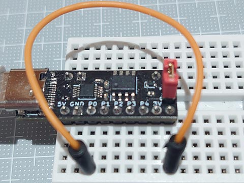
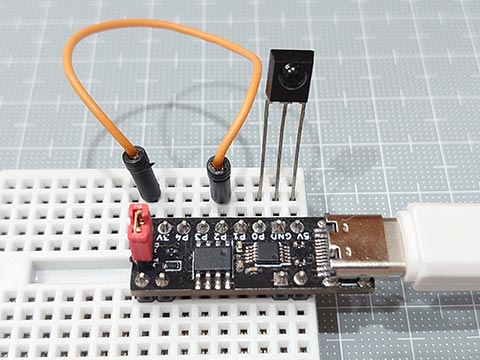
Rx(CH340E)とシリアル出力ピン(Tx)をワイヤーでつないでいます。
(スケッチ書き込み時は、ワイヤーを外します。)
ちなみにこれらを、UNO R4 minima と USBシリアル変換モジュールで試したらちょくちょく文字化けして使い物にはなりませんでした。
202duino で シリアル通信:放課後マイコンクラブ:SSブログ
https://hello-world.blog.ss-blog.jp/2023-05-29
ただ、ハードウェアシリアルを使うと、ほとんどフラッシュメモリの空きがなくなる問題が出てきます。
そこで、
・送信だけ
・送信中に他の事はできない
・高速な通信はできない
という制限はあるもののレジスタを直接たたかずにArduinoの機能だけで自力でシリアル出力をしてみました。
micros()でタイミングをとるバージョンと、delayMicroseconds()でタイミングをとるバージョンを作りました。
以下の1秒毎に「Hello world!」を送信するスケッチで、どちらも余裕で1kBを切れました。
// Arduino based serial output

#define TX    0                 // TX pin
#define BAUD  9600              // baud rate

void setup() {
    pinMode( TX ,  OUTPUT );
    digitalWrite( TX, HIGH );
}

void loop() {
    char text[] = "Hello world!\n";
    for(uint8_t i = 0; text[i]; i++ )   inoTX( text[i] );
    delay(1000);
}

void inoTX( uint8_t c ) {       // *** OK up to 38400bps at 20MHz(ATtiny202) ***
    uint32_t  us = micros();
    digitalWrite( TX,  LOW );                   // start bit
    while( micros() - us < (1000000 / BAUD) );
    us += (1000000 / BAUD);
    for(uint8_t i = 0; i < 8; i++ ) {           // data bits
      digitalWrite( TX, ( c >> i ) & 1 );
      while( micros() - us < (1000000 / BAUD) );
      us += (1000000 / BAUD);
    }
    digitalWrite( TX, HIGH );                   // stop bit
    while( micros() - us < (1000000 / BAUD) );
}
別バージョン ー delayMicroseconds()版
void inoTx( uint8_t c ) {       // *** OK up to 19200bps at 20MHz(ATtiny202) ***
    digitalWrite( TX,  LOW );                   // start bit
    delayMicroseconds( 1000000 / BAUD );
    for(uint8_t i = 0; i < 8; i++ ) {           // data bits
      digitalWrite( TX, ( c >> i ) & 1 );
      delayMicroseconds( 1000000 / BAUD );
    }
    digitalWrite( TX, HIGH );                   // stop bit
    delayMicroseconds( 1000000 / BAUD );
}
Rx(CH340E)とシリアル出力ピン(Tx)をワイヤーでつないでいます。
(スケッチ書き込み時は、ワイヤーを外します。)
ちなみにこれらを、UNO R4 minima と USBシリアル変換モジュールで試したらちょくちょく文字化けして使い物にはなりませんでした。
リモコンのデータ形式:Apple Remote [Arduino]
Apple Remote 再調査。
Apple Remote - Wikipedia
https://en.wikipedia.org/wiki/Apple_Remote
このページの説明と、取得データの解読がやっとできました。
wikipediaの解説は、32bitのデータを、16bitに区切って、下位の16bitを上位から説明し、続いて上位16bitを上位から説明しているのでわかりにくかったのでした。
つまり、32bitのデータを上から、、
(MSB)
Device ID (8bit) …………… ペアリングコマンドで変更可
Command (7bit) …………… コマンドページの実際のコマンド
Odd Parity (1bit) …………… 全32bitを足すと1になる
Vender (7bit) ………………… 0x43fで固定
Command Page (5bit) ……ペアリング等は 0x0、通常のボタンは 0xe
(LSB)
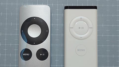
■Apple Remote(初代)A1156
[MENU]
⏯
⏭
⏮
+
ー
NEC : 32bit 0x610387EE / 0b 01100001 - 0000001 - 1 - 10000111111 - 01110
NEC : 32bit 0x610587EE / 0b 01100001 - 0000010 - 1 - 10000111111 - 01110
NEC : 32bit 0x610687EE / 0b 01100001 - 0000011 - 0 - 10000111111 - 01110
NEC : 32bit 0x610987EE / 0b 01100001 - 0000100 - 1 - 10000111111 - 01110
NEC : 32bit 0x610A87EE / 0b 01100001 - 0000101 - 0 - 10000111111 - 01110
NEC : 32bit 0x610C87EE / 0b 01100001 - 0000110 - 0 - 10000111111 - 01110
DeviceID Command OP Vender(0x43f) CmdPage
旧リモコンの解除 (MENU + |<< を同時に6秒間以上)
NEC : 32bit 0x610487E0 / 0b 01100001 - 0000010 - 0 - 10000111111 - 00000
新リモコンの登録 (MENU + >>| を同時に6秒間以上)
NEC : 32bit 0x610287E0 / 0b 01100001 - 0000001 - 0 - 10000111111 - 00000
■Apple Remote(第2世代)
[MENU]
⏯
〇 (中央ボタン)
˃
⌃
˂
⌃
NEC : 32bit 0x3D0387EE / 0b 00111101 - 0000001 - 1 - 10000111111 - 01110
NEC : 32bit 0x3D0587EE / 0b 00111101 - 0000010 - 1 - 10000111111 - 01110
NEC : 32bit 0x3D0587EE / 0b 00111101 - 0000010 - 1 - 10000111111 - 01110
NEC : 32bit 0x3D0687EE / 0b 00111101 - 0000011 - 0 - 10000111111 - 01110
NEC : 32bit 0x3D0A87EE / 0b 00111101 - 0000101 - 0 - 10000111111 - 01110
NEC : 32bit 0x3D0987EE / 0b 00111101 - 0000100 - 1 - 10000111111 - 01110
NEC : 32bit 0x3D0C87EE / 0b 00111101 - 0000110 - 0 - 10000111111 - 01110
また別の話だけど、、
プロトコル(protocol) = フォーマット(format) + プロシージャ(procedure) ってことらしい。
たとえば、Apple Remote は、、
「The Apple Remote uses a modified NEC IR protocol which consists of a differential PPM encoding on a 1:3 duty cycle 38 kHz 950 nm infrared carrier. There are 32 bits of encoded data between the AGC leader and the stop bit:」
「While the Apple Remote uses the NEC IR protocol for the timing, the 32-bit data package is in a different format. It consists of two 16 bit LSB words.」
とあり、赤外線の送り方はNEC方式だが、32bitのデータ形式はアップル独自のデータ(フォーマット)ということらしい。
Apple Remote - Wikipedia
https://en.wikipedia.org/wiki/Apple_Remote
このページの説明と、取得データの解読がやっとできました。
wikipediaの解説は、32bitのデータを、16bitに区切って、下位の16bitを上位から説明し、続いて上位16bitを上位から説明しているのでわかりにくかったのでした。
つまり、32bitのデータを上から、、
(MSB)
Device ID (8bit) …………… ペアリングコマンドで変更可
Command (7bit) …………… コマンドページの実際のコマンド
Odd Parity (1bit) …………… 全32bitを足すと1になる
Vender (7bit) ………………… 0x43fで固定
Command Page (5bit) ……ペアリング等は 0x0、通常のボタンは 0xe
(LSB)
■Apple Remote(初代)A1156
[MENU]
⏯
⏭
⏮
+
ー
NEC : 32bit 0x610387EE / 0b 01100001 - 0000001 - 1 - 10000111111 - 01110
NEC : 32bit 0x610587EE / 0b 01100001 - 0000010 - 1 - 10000111111 - 01110
NEC : 32bit 0x610687EE / 0b 01100001 - 0000011 - 0 - 10000111111 - 01110
NEC : 32bit 0x610987EE / 0b 01100001 - 0000100 - 1 - 10000111111 - 01110
NEC : 32bit 0x610A87EE / 0b 01100001 - 0000101 - 0 - 10000111111 - 01110
NEC : 32bit 0x610C87EE / 0b 01100001 - 0000110 - 0 - 10000111111 - 01110
DeviceID Command OP Vender(0x43f) CmdPage
旧リモコンの解除 (MENU + |<< を同時に6秒間以上)
NEC : 32bit 0x610487E0 / 0b 01100001 - 0000010 - 0 - 10000111111 - 00000
新リモコンの登録 (MENU + >>| を同時に6秒間以上)
NEC : 32bit 0x610287E0 / 0b 01100001 - 0000001 - 0 - 10000111111 - 00000
■Apple Remote(第2世代)
[MENU]
⏯
〇 (中央ボタン)
˃
⌃
˂
⌃
NEC : 32bit 0x3D0387EE / 0b 00111101 - 0000001 - 1 - 10000111111 - 01110
NEC : 32bit 0x3D0587EE / 0b 00111101 - 0000010 - 1 - 10000111111 - 01110
NEC : 32bit 0x3D0587EE / 0b 00111101 - 0000010 - 1 - 10000111111 - 01110
NEC : 32bit 0x3D0687EE / 0b 00111101 - 0000011 - 0 - 10000111111 - 01110
NEC : 32bit 0x3D0A87EE / 0b 00111101 - 0000101 - 0 - 10000111111 - 01110
NEC : 32bit 0x3D0987EE / 0b 00111101 - 0000100 - 1 - 10000111111 - 01110
NEC : 32bit 0x3D0C87EE / 0b 00111101 - 0000110 - 0 - 10000111111 - 01110
また別の話だけど、、
プロトコル(protocol) = フォーマット(format) + プロシージャ(procedure) ってことらしい。
たとえば、Apple Remote は、、
「The Apple Remote uses a modified NEC IR protocol which consists of a differential PPM encoding on a 1:3 duty cycle 38 kHz 950 nm infrared carrier. There are 32 bits of encoded data between the AGC leader and the stop bit:」
「While the Apple Remote uses the NEC IR protocol for the timing, the 32-bit data package is in a different format. It consists of two 16 bit LSB words.」
とあり、赤外線の送り方はNEC方式だが、32bitのデータ形式はアップル独自のデータ(フォーマット)ということらしい。
リモコンのデータ形式:KOIZUMI照明 [Arduino]
KOIZUMI照明リモコンのデータ形式をのぞいてみた。
NEC形式でした。
■KOIZUMI照明リモコン KRH-TA-8A
消灯
オフタイマー30min
タイマー解除
順送り(全灯→調光→保安灯→消灯→)
▲ 調光 (repeat codeあり)
▼ 調光 (repeat codeあり)
調光(調光状態(記憶値)で点灯)
保安灯(保安灯の点灯と明るさ調節(5段階調光))
ch.I
NEC : 32bit 0xFF006E80 / 0b 11111111 00000000 01101110 10000000
NEC : 32bit 0xFE016E80 / 0b 11111110 00000001 01101110 10000000
NEC : 32bit 0xFC036E80 / 0b 11111100 00000011 01101110 10000000
NEC : 32bit 0xFB046E80 / 0b 11111011 00000100 01101110 10000000
NEC : 32bit 0xFA056E80 / 0b 11111010 00000101 01101110 10000000 (repeat codeあり)
NEC : 32bit 0xF9066E80 / 0b 11111001 00000110 01101110 10000000 (repeat codeあり)
NEC : 32bit 0xED126E80 / 0b 11101101 00010010 01101110 10000000
NEC : 32bit 0xEC136E80 / 0b 11101100 00010011 01101110 10000000
ch.II
NEC : 32bit 0x7F806E80 / 0b 01111111 10000000 01101110 10000000
NEC : 32bit 0x7E816E80 / 0b 01111110 10000001 01101110 10000000
NEC : 32bit 0x7C836E80 / 0b 01111100 10000011 01101110 10000000
NEC : 32bit 0x7B846E80 / 0b 01111011 10000100 01101110 10000000
NEC : 32bit 0x7A856E80 / 0b 01111010 10000101 01101110 10000000 (repeat codeあり)
NEC : 32bit 0x79866E80 / 0b 01111001 10000110 01101110 10000000 (repeat codeあり)
NEC : 32bit 0x6D926E80 / 0b 01101101 10010010 01101110 10000000
NEC : 32bit 0x6C936E80 / 0b 01101100 10010011 01101110 10000000
ch.III
NEC : 32bit 0x857A6E80 / 0b 10000101 01111010 01101110 10000000
NEC : 32bit 0x8D726E80 / 0b 10001101 01110010 01101110 10000000
NEC : 32bit 0x8C736E80 / 0b 10001100 01110011 01101110 10000000
NEC : 32bit 0x86796E80 / 0b 10000110 01111001 01101110 10000000
NEC : 32bit 0x956A6E80 / 0b 10010101 01101010 01101110 10000000 (repeat codeあり)
NEC : 32bit 0x946B6E80 / 0b 10010100 01101011 01101110 10000000 (repeat codeあり)
NEC : 32bit 0x87786E80 / 0b 10000111 01111000 01101110 10000000
NEC : 32bit 0x847B6E80 / 0b 10000100 01111011 01101110 10000000
最初の(下から)16ビットは 6E80で、KOIZUMIのカスタマーコードと思われる。
次の8ビットが実質のデータで、最後の8ビットはエラーチェック用。
ch.Iとch.IIについては、データ部の0~4ビット目が明かりのデータで、7ビット目がチャンネルのようだけど、ch.IIIではその規則性が消失。
もともとch.Iとch.IIしかなかったところに、ch.IIIを無理くり追加したのかな?
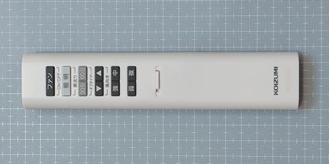
■KOIZUMI照明ファンリモコン KRH-TE-10IF
風向き ▲
風向き ▼
強
中
弱
微
照明(順送り)
ファンON/OFF
オフタイマー 30分
オフタイマー 60分
CH I
NEC : 32bit 0xCC336E80 0b 11001100 00110011 01101110 10000000
NEC : 32bit 0xCB346E80 0b 11001011 00110100 01101110 10000000
NEC : 32bit 0xCA356E80 0b 11001010 00110101 01101110 10000000
NEC : 32bit 0xC9366E80 0b 11001001 00110110 01101110 10000000
NEC : 32bit 0xC8376E80 0b 11001000 00110111 01101110 10000000
NEC : 32bit 0xC7386E80 0b 11000111 00111000 01101110 10000000
NEC : 32bit 0xC6396E80 0b 11000110 00111001 01101110 10000000
NEC : 32bit 0xC53A6E80 0b 11000101 00111010 01101110 10000000
NEC : 32bit 0xC43B6E80 0b 11000100 00111011 01101110 10000000
NEC : 32bit 0xC33C6E80 0b 11000011 00111100 01101110 10000000
CH II
NEC : 32bit 0x4CB36E80 0b 01001100 10110011 01101110 10000000
NEC : 32bit 0x4BB46E80 0b 01001011 10110100 01101110 10000000
NEC : 32bit 0x4AB56E80 0b 01001010 10110101 01101110 10000000
NEC : 32bit 0x49B66E80 0b 01001001 10110110 01101110 10000000
NEC : 32bit 0x48B76E80 0b 01001000 10110111 01101110 10000000
NEC : 32bit 0x47B86E80 0b 01000111 10111000 01101110 10000000
NEC : 32bit 0x46B96E80 0b 01000110 10111001 01101110 10000000
NEC : 32bit 0x45BA6E80 0b 01000101 10111010 01101110 10000000
NEC : 32bit 0x44BB6E80 0b 01000100 10111011 01101110 10000000
NEC : 32bit 0x43BC6E80 0b 01000011 10111100 01101110 10000000
8ビットの実質のデータ部分で、0~5ビット目が操作データで、7ビット目がチャンネルのよう。
NEC形式でした。
■KOIZUMI照明リモコン KRH-TA-8A
消灯
オフタイマー30min
タイマー解除
順送り(全灯→調光→保安灯→消灯→)
▲ 調光 (repeat codeあり)
▼ 調光 (repeat codeあり)
調光(調光状態(記憶値)で点灯)
保安灯(保安灯の点灯と明るさ調節(5段階調光))
ch.I
NEC : 32bit 0xFF006E80 / 0b 11111111 00000000 01101110 10000000
NEC : 32bit 0xFE016E80 / 0b 11111110 00000001 01101110 10000000
NEC : 32bit 0xFC036E80 / 0b 11111100 00000011 01101110 10000000
NEC : 32bit 0xFB046E80 / 0b 11111011 00000100 01101110 10000000
NEC : 32bit 0xFA056E80 / 0b 11111010 00000101 01101110 10000000 (repeat codeあり)
NEC : 32bit 0xF9066E80 / 0b 11111001 00000110 01101110 10000000 (repeat codeあり)
NEC : 32bit 0xED126E80 / 0b 11101101 00010010 01101110 10000000
NEC : 32bit 0xEC136E80 / 0b 11101100 00010011 01101110 10000000
ch.II
NEC : 32bit 0x7F806E80 / 0b 01111111 10000000 01101110 10000000
NEC : 32bit 0x7E816E80 / 0b 01111110 10000001 01101110 10000000
NEC : 32bit 0x7C836E80 / 0b 01111100 10000011 01101110 10000000
NEC : 32bit 0x7B846E80 / 0b 01111011 10000100 01101110 10000000
NEC : 32bit 0x7A856E80 / 0b 01111010 10000101 01101110 10000000 (repeat codeあり)
NEC : 32bit 0x79866E80 / 0b 01111001 10000110 01101110 10000000 (repeat codeあり)
NEC : 32bit 0x6D926E80 / 0b 01101101 10010010 01101110 10000000
NEC : 32bit 0x6C936E80 / 0b 01101100 10010011 01101110 10000000
ch.III
NEC : 32bit 0x857A6E80 / 0b 10000101 01111010 01101110 10000000
NEC : 32bit 0x8D726E80 / 0b 10001101 01110010 01101110 10000000
NEC : 32bit 0x8C736E80 / 0b 10001100 01110011 01101110 10000000
NEC : 32bit 0x86796E80 / 0b 10000110 01111001 01101110 10000000
NEC : 32bit 0x956A6E80 / 0b 10010101 01101010 01101110 10000000 (repeat codeあり)
NEC : 32bit 0x946B6E80 / 0b 10010100 01101011 01101110 10000000 (repeat codeあり)
NEC : 32bit 0x87786E80 / 0b 10000111 01111000 01101110 10000000
NEC : 32bit 0x847B6E80 / 0b 10000100 01111011 01101110 10000000
最初の(下から)16ビットは 6E80で、KOIZUMIのカスタマーコードと思われる。
次の8ビットが実質のデータで、最後の8ビットはエラーチェック用。
ch.Iとch.IIについては、データ部の0~4ビット目が明かりのデータで、7ビット目がチャンネルのようだけど、ch.IIIではその規則性が消失。
もともとch.Iとch.IIしかなかったところに、ch.IIIを無理くり追加したのかな?
■KOIZUMI照明ファンリモコン KRH-TE-10IF
風向き ▲
風向き ▼
強
中
弱
微
照明(順送り)
ファンON/OFF
オフタイマー 30分
オフタイマー 60分
CH I
NEC : 32bit 0xCC336E80 0b 11001100 00110011 01101110 10000000
NEC : 32bit 0xCB346E80 0b 11001011 00110100 01101110 10000000
NEC : 32bit 0xCA356E80 0b 11001010 00110101 01101110 10000000
NEC : 32bit 0xC9366E80 0b 11001001 00110110 01101110 10000000
NEC : 32bit 0xC8376E80 0b 11001000 00110111 01101110 10000000
NEC : 32bit 0xC7386E80 0b 11000111 00111000 01101110 10000000
NEC : 32bit 0xC6396E80 0b 11000110 00111001 01101110 10000000
NEC : 32bit 0xC53A6E80 0b 11000101 00111010 01101110 10000000
NEC : 32bit 0xC43B6E80 0b 11000100 00111011 01101110 10000000
NEC : 32bit 0xC33C6E80 0b 11000011 00111100 01101110 10000000
CH II
NEC : 32bit 0x4CB36E80 0b 01001100 10110011 01101110 10000000
NEC : 32bit 0x4BB46E80 0b 01001011 10110100 01101110 10000000
NEC : 32bit 0x4AB56E80 0b 01001010 10110101 01101110 10000000
NEC : 32bit 0x49B66E80 0b 01001001 10110110 01101110 10000000
NEC : 32bit 0x48B76E80 0b 01001000 10110111 01101110 10000000
NEC : 32bit 0x47B86E80 0b 01000111 10111000 01101110 10000000
NEC : 32bit 0x46B96E80 0b 01000110 10111001 01101110 10000000
NEC : 32bit 0x45BA6E80 0b 01000101 10111010 01101110 10000000
NEC : 32bit 0x44BB6E80 0b 01000100 10111011 01101110 10000000
NEC : 32bit 0x43BC6E80 0b 01000011 10111100 01101110 10000000
8ビットの実質のデータ部分で、0~5ビット目が操作データで、7ビット目がチャンネルのよう。
タグ:リモコン
赤外線リモコンの受信を簡単なスケッチで。 [Arduino]
以前に赤外線リモコンの送信データを分析するスケッチを作りました。
赤外線リモコン (解析の友):放課後マイコンクラブ:SSブログ
https://hello-world.blog.ss-blog.jp/2011-05-19
ただ日本ではNEC形式、AEHA (家電製品協会)形式、SIRC(SONY)形式の3つを押さえれば、たいていなんとかなるのではないかと思い、解析ではなく、受信&デコードだけのスケッチを作りました。
コンパクトなスケッチですが、シリアルでデータを送信するので、容量的にATtiny202には載せられず、ATtiny402/412ならOKなサイズになりました。
NEC形式、SIRC(SONY)形式は32ビット整数として受け取り、AEHA (家電製品協会)形式は、データ配列とその長さを受け取ることにしました。
うちの霧ヶ峰のリモコン(AEHA形式)は、以前調べた規定の最大ビット数より大きいものでした。
あと、最近のSONYのリモコンは電源ボタン以外はBluetooth?(テレビ側は純粋な赤外線リモコンも対応)
Uno R4は32ビットだからなのか、16ビット以上の左シフト演算の際に「1UL」とせずに、「1」としちゃっても正常動作した。ATtiny412で動作確認したときに「1」の16ビット以上の左シフトが動作不良で発覚。
あと前回同様に、赤外線リモコン受信モジュールは、Arduino直刺しするためにI/Oピンを電源がわりに使っています。赤外線リモコン受信モジュールの消費電流はわずかなので大丈夫だと思う。ノイズ対策はごめん。
// IR Receive and Decode
#define IR_IN   2           // IR Receiver pin

void setup() {
  pinMode( IR_IN , INPUT );                     // input  Vout(active low, negative logic)
    pinMode( 3 ,  OUTPUT ); digitalWrite( 3, LOW  );  // LOW  (*use as GND)
    pinMode( 4 ,  OUTPUT ); digitalWrite( 4, HIGH );  // HIGH (*use as Vcc)
  Serial.begin(115200);
}

void loop() {
  uint32_t  irData = 0;
  uint8_t   irProtocol = 0, irBit = 0, irArray[20] = {0};

  // ****** Receive and Decode IR signals ******
  uint16_t  us = pulseIn( IR_IN, LOW , 65535 ); // Judge the protocol by the length of the leader section (usec.)
  if      ( us > 2000 && us <  3000 ) {         //  *** SIRC ***
      irProtocol = 'S';                         //  T=600us, ON/OFF : leader= 4T/1T, 0=1T/1T, 1=2T/1T
      for(;(us = pulseIn( IR_IN, LOW , 3000 )); irBit++)
        if( us > 1000 && us <  1500 ) irData |= (1UL << irBit);
  }else if( us > 3500 && us <  5000 ) {         //  *** AEHA ***
      irProtocol = 'A';                         //  T=425us, ON/OFF : leader= 8T/4T, 0=1T/1T, 1=1T/3T, stop=1T
      while( digitalRead( IR_IN ) );
      for(;(us = pulseIn( IR_IN, HIGH, 4000 )); irBit++)
        if( us > 1050 && us <  1500 ) irArray[ irBit / 8 ] |= (1 << (irBit % 8) );
  }else if( us > 7200 && us < 11000 ) {         //  *** NEC ***
      irProtocol = 'N';                         //  T=560us, ON/OFF : leader=16T/8T, 0=1T/1T, 1=1T/3T, stop=1T
      while( digitalRead( IR_IN ) );
      for(;(us = pulseIn( IR_IN, HIGH, 3000 )); irBit++)
        if( us > 1350 && us <  2000 ) irData |= (1UL << irBit);
  }else return;

  // ****** Display results by protocol ******
  Serial.print( irProtocol == 'S' ? "SIRC: " : irProtocol == 'A' ? "AEHA: " : "NEC : " );
  if( !irBit ) {
    Serial.println( " (repeat code) " );
    return;
  }
  Serial.print( irBit );
  Serial.print( "bit" );
  if( irProtocol == 'A' ) {
    for( uint8_t i = 0; i < ( (irBit + 7) / 8 ); i++ ) {
      Serial.print((irArray[i] < 0x10) ? " 0x0" : " 0x" );
      Serial.print( irArray[i], HEX );
    }
  } else {
      Serial.print( " 0x" );
      Serial.print( irData, HEX );
  }
  Serial.println("");
}
タグ:リモコン


