ATtiny202 正弦波のノイズ問題 TCAで解決! [Arduino]
ATtiny202 正弦波のノイズ問題が解決できました。
Timer/Counter Type A (TCA) は megaTinyCore のデフォルトで millis()/micros() に使われていたため、今まで手を出さなかったのですが、TCBにはない、PERにバッファーが付いた PERBUF や、CMPnにバッファーが付いた CMPnBUF を使わないとなんともならないようでした。
そこで、以下のサンプルプログラムとデータシートを見ながら作ってみました。
Getting Started with TCA
https://www.microchip.com/content/dam/mchp/documents/MCU08/ApplicationNotes/ApplicationNotes/TB3217-Getting-Started-with-TCA-DS90003217.pdf
★はまったところ
はまったところは、megaTinyCore特有のところでした。
・PORTMUXの代替ピンが使用されていた
PA3 (megaTinyCore 4番ピン) → PA7 (megaTinyCore 1番ピン)
・TCAの Split Mode が使用されていた
いくら PERBUF や CMP0BUF を変更しても値が変わらない、、
なぜなら、Split Mode にはこれらがないから。
TCA0.SINGLE.CTRLD = 0; でSplit Mode から Normal Mode に戻す必要があった。
この設定は 「millis()/micros() Timer;"Disabled(save flash)"」にしても有効。
megaTinyCoreでmillis()/micros()は使わないけど、PWMには使うから。
megaTinyCore_megaavr_extras_TakingOverTCA0.md at master · SpenceKonde_megaTinyCore · GitHub
https://github.com/SpenceKonde/megaTinyCore/blob/master/megaavr/extras/TakingOverTCA0.md
以下、スケッチ。millis()/micros() の割り込みは解除してあります。
//  megaTinyCore(mTC) ATtiny202/212/402/412 Sine Wave with TCA
#include <avr/io.h>
#include <util/delay.h>

static const uint16_t OCTAVE9[] = { 7023, 7441, 7883, 8352, 8848, 9375, 9932, 10523,11148,11811,12513,13258 };
static const uint8_t  SINE256[] = {
    0,  0,  0,  0,  1,  1,  1,  2,  2,  3,  4,  5,  5,  6,  7,  9,  10, 11, 12, 14, 15, 17, 18, 20, 21, 23, 25, 27, 29, 31, 33, 35,
   37, 40, 42, 44, 47, 49, 52, 54, 57, 59, 62, 65, 67, 70, 73, 76,  79, 82, 85, 88, 90, 93, 97,100,103,106,109,112,115,118,121,124,
  128,131,134,137,140,143,146,149,152,155,158,162,165,167,170,173, 176,179,182,185,188,190,193,196,198,201,203,206,208,211,213,215,
  218,220,222,224,226,228,230,232,234,235,237,238,240,241,243,244, 245,246,248,249,250,250,251,252,253,253,254,254,254,255,255,255,
  255,255,255,255,254,254,254,253,253,252,251,250,250,249,248,246, 245,244,243,241,240,238,237,235,234,232,230,228,226,224,222,220,
  218,215,213,211,208,206,203,201,198,196,193,190,188,185,182,179, 176,173,170,167,165,162,158,155,152,149,146,143,140,137,134,131,
  128,124,121,118,115,112,109,106,103,100, 97, 93, 90, 88, 85, 82,  79, 76, 73, 70, 67, 65, 62, 59, 57, 54, 52, 49, 47, 44, 42, 40,
   37, 35, 33, 31, 29, 27, 25, 23, 21, 20, 18, 17, 15, 14, 12, 11,  10,  9,  7,  6,  5,  5,  4,  3,  2,  2,  1,  1,  1,  0,  0,  0 };

void setup(){           // Register Settings
  PORTA.DIRSET    = PIN7_bm;    // PA7 OUTPUT (mTC:1)
  //PORTMUX.CTRLC = 0;          // turn off TCA port multiplexer (PA7(mTC:1) to default PA3(mTC:4))
  TCA0.SINGLE.CTRLD   = 0;      // turn off split mode
  TCA0.SINGLE.CTRLC   = 0;      // PWM output pins override - disable
  TCA0.SINGLE.CTRLB   = TCA_SINGLE_CMP0EN_bm | TCA_SINGLE_WGMODE_SINGLESLOPE_gc;
  TCA0.SINGLE.INTCTRL = 0;      // turn off Arduino(mTC) time system
  TCA0.SINGLE.PERBUF  = 0xff;   // top value = 255
  TCA0.SINGLE.CMP0BUF = 0;      // output value
  TCA0.SINGLE.CTRLA   = TCA_SINGLE_CLKSEL_DIV1_gc | TCA_SINGLE_ENABLE_bm; // 20MHz / 1 / 256 -> 78,125Hz
}

void loop(){
  sineWave( 60,  500);          // C4
  sineWave( 64,  500);          // E4
  sineWave( 67,  500);          // G4
  sineWave( 72, 2000);          // C5
  _delay_ms(1000);
}

void sineWave(uint8_t midiNum, uint16_t msDuration) {
  uint16_t i, di = OCTAVE9[ midiNum % 12 ] >> (10 - midiNum / 12);  // 256 times the Wave Table subscript to advance in one cycle
  uint32_t cycDuration = F_CPU / 256 / 1000 * msDuration;           // Convert duration to number of cycles
  do {
    TCA0.SINGLE.CMP0BUF = SINE256[ (i += di) >> 8 ];        // 8bit PWM (78,125Hz)
      while( !(TCA0.SINGLE.INTFLAGS & TCA_SINGLE_OVF_bm) ); // Waiting for TCA0 overflow
      TCA0.SINGLE.INTFLAGS = TCA_SINGLE_OVF_bm;             // cleared by writing a '1'
  } while( --cycDuration );                                 // Exit if note data is 0
  TCA0.SINGLE.CMP0BUF = 0;                                  // Set output to 0
}
よくある安いI2C OLEDについて調べてみた。 [Arduino]
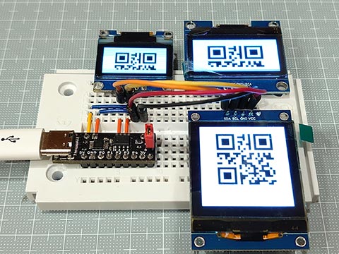
以下3つのよくあるI2CのOLEDだけど、いろいろ調べたらほぼ同じ操作でいけると判明。
・0.96インチ , 128x64 , SSD1306
・1.3インチ, 128x64, SH1106
・1.5インチ, 128x128, SH1107
★共通なところ
・5VのArduinoで、プルアップ抵抗なしで動く。
・アドレスが 0x78 (Wireライブラリでは 0x3C と1ビットずらす)
・画像メモリーの使い方、縦8ドットで1バイトが横に128個。これが縦に8ページ(あるいは16ページ)
・コマンドも大体同じっぽい
★それぞれで違うところ
*** 0.96'', 128x64 , SSD1306 ***
初期化コマンドは、0x8D, 0x14 の Enable charge pump と、0xAF の switch on OLEDの2つだけでとりあえず表示できる。
メモリがページをまたいでリニアになっているので、自然に折り返しできる。
ピンは GND VCC SCL SDA の順。
*** 1.3'', 128x64, SH1106 ***
初期化コマンドは、0xAF だけでとりあえずOK。
メモリはページをまたげない。
制御チップは132x64ドットでできているようだが、OLEDは128x64でできているので左右に2ドットずつ表示されない領域がある。
ピンは VCC GND SCL SDA の順。電源が0.96インチと逆で間違えると壊れるので注意。
*** 1.5'', 128x128, SH1107 ***
こちらも初期化コマンドは、0xAF だけでとりあえずOK。
同様にメモリはページをまたげない。
ピンは VCC GND SCL SDA の順。電源注意。
これはGME128128-01-IIC Ver 2.0での話。Ver 3は SSD1327 ?
// tinyOLEDdemo - controlling an I²C OLED (SSD1306/SH1106/SH1107) with an ATtiny202
//
// A big thank you to Stefan Wagner
// Project Files (Github):  https://github.com/wagiminator
// License: http://creativecommons.org/licenses/by-sa/3.0/

#include <avr/io.h>
#include <util/delay.h>

const uint8_t img_i[] = {   32,   32, // px
  0x00, 0x00, 0x00, 0x00, 0x00, 0x00, 0x00, 0x00, 0x00, 0x00, 0x00, 0x00, 0x00, 0x00, 0x00, 0x00,
  0x00, 0x00, 0x00, 0x82, 0xee, 0xfe, 0xfe, 0xfc, 0xf8, 0x70, 0x20, 0x00, 0x00, 0x00, 0x00, 0x00,
  0x00, 0x00, 0x00, 0x00, 0x00, 0x00, 0x00, 0x00, 0x00, 0x00, 0x00, 0x00, 0x80, 0xc0, 0xe0, 0xf0,
  0xf8, 0x7e, 0xff, 0xff, 0xef, 0xc7, 0x03, 0x01, 0x00, 0x00, 0x00, 0x00, 0x00, 0x00, 0x00, 0x00,
  0x00, 0x00, 0x00, 0x20, 0x20, 0x30, 0x10, 0x18, 0x1c, 0x0e, 0x0f, 0x07, 0x07, 0x03, 0x01, 0x01,
  0x00, 0x00, 0xff, 0xff, 0xff, 0xff, 0x00, 0x00, 0x00, 0x00, 0x00, 0x00, 0x00, 0x00, 0x00, 0x00,
  0x00, 0x00, 0x00, 0x00, 0x00, 0x00, 0x00, 0x00, 0x00, 0x00, 0x00, 0x00, 0x00, 0x00, 0x00, 0x00,
  0x00, 0x1e, 0x3f, 0x7f, 0x3f, 0x3f, 0x00, 0x00, 0x00, 0x00, 0x00, 0x00, 0x00, 0x00, 0x00, 0x00
};
const uint8_t img_qr[] = {  23,   23, // px
  0xff, 0x01, 0x7d, 0x45, 0x45, 0x45, 0x7d, 0x01, 0xff, 0x2b, 0xcb, 0x71, 0xdf, 0x01, 0xff, 0x01,
  0x7d, 0x45, 0x45, 0x45, 0x7d, 0x01, 0xff, 0xff, 0x59, 0x55, 0x7d, 0x71, 0x49, 0x67, 0x55, 0xf9,
  0x3d, 0xc2, 0x8b, 0x57, 0x91, 0x3d, 0x77, 0xc9, 0x27, 0xb9, 0x93, 0x71, 0xf7, 0xff, 0xff, 0xc0,
  0xdf, 0xd1, 0xd1, 0xd1, 0xdf, 0xc0, 0xff, 0xc1, 0xf3, 0xfa, 0xcd, 0xd5, 0xc8, 0xc5, 0xea, 0xe6,
  0xe8, 0xd8, 0xcb, 0xec, 0xff
};
// ---- I2C Master Implementation (Write only) ---------------------------------

#define I2C_FREQ  800000UL                        // I2C clock frequency in Hz
void I2C_init(void) {                             // I2C init function
  TWI0.MBAUD   = ((F_CPU / I2C_FREQ) - 10) / 2;   //   set TWI master BAUD rate (simplified BAUD calculation)
  TWI0.MCTRLA  = TWI_ENABLE_bm;                   //   enable TWI master
  TWI0.MSTATUS = TWI_BUSSTATE_IDLE_gc;            //   set bus state to idle
}
void I2C_start(uint8_t addr) {                    // I2C start transmission
  TWI0.MADDR = addr;                              //   start sending address
}
void I2C_stop(void) {                             // I2C stop transmission
  while (~TWI0.MSTATUS & TWI_WIF_bm);             //   wait for last transfer to complete
  TWI0.MCTRLB = TWI_MCMD_STOP_gc;                 //   send stop condition
}
void I2C_write(uint8_t data) {                    // I2C transmit one data byte to the slave, ignore ACK bit
  while (~TWI0.MSTATUS & TWI_WIF_bm);             //   wait for last transfer to complete
  TWI0.MDATA = data;                              //   start sending data byte
}

// ---- OLED Implementation ----------------------------------------------------

#define OLED_ADDR       0x78             // OLED write address (Wire lib.:0x3c)
#define OLED_CMD_MODE   0x00             // set command mode
#define OLED_DAT_MODE   0x40             // set data mode

const uint8_t OLED_INIT_CMD[] = {        // OLED init settings
//0xA8, 0x7F,           // set multiplex (HEIGHT-1): 0x1F(128x32), 0x3F(128x64), 0x7F(128x128)
//0x22, 0x00, 0x0f,     // set min and max page: 0x07(128x64), 0x0F(128x128)
//0x20, 0x00,           // set horizontal memory addressing mode
//0xDA, 0x12,           // set COM pins hardware configuration to alternative
  0x8D, 0x14,           // enable charge pump (for SSD1306)
  0xAF                  // switch on OLED
};

void OLED_init(void) {                    // OLED init function
  I2C_init();                             //   initialize I2C first
  I2C_start(OLED_ADDR);                   //   start transmission to OLED
  I2C_write(OLED_CMD_MODE);               //   set command mode
  for (uint8_t i=0; i<sizeof(OLED_INIT_CMD); i++) I2C_write(OLED_INIT_CMD[i]); //   send the command bytes
  I2C_stop();                             //   stop transmission
}

void OLED_cursor(uint8_t xpos, uint8_t ypos) {// OLED set the cursor
  xpos +=2;                               //  (for SH1106 (132x64)
  I2C_start(OLED_ADDR);                   //   start transmission to OLED
  I2C_write(OLED_CMD_MODE);               //   set command mode
  I2C_write(xpos & 0x0F);                 //   set low nibble of start column
  I2C_write(0x10 | (xpos >> 4));          //   set high nibble of start column
  I2C_write(0xB0 | (ypos & 0x0f));        //   set start page
  I2C_stop();                             //   stop transmission
}

void OLED_clear(uint16_t p) {             // OLED clear screen with pattern
  if( p < 256 ) p |= p << 8;
  for(uint8_t pg=0; pg<16; pg++){
    OLED_cursor(0, pg);                   //   set cursor at upper left corner
    I2C_start(OLED_ADDR);                 //   start transmission to OLED
    I2C_write(OLED_DAT_MODE);             //   set data mode
    for(uint8_t c=64; c; c--) {
      I2C_write(p & 0xff);                //   fill the screen
      I2C_write(p >> 8  );
    }
    I2C_stop();                           //   stop transmission
  }
}

void OLED_image(uint8_t xpos, uint8_t ypos, uint8_t *d) {// OLED set image
  const uint8_t w=*d++, h=*d++;
  for(uint8_t y=0; y<(h+7)/8; y++) {
    OLED_cursor(xpos, ypos + y);          //   set the cursor
    I2C_start(OLED_ADDR);                 //   start transmission to OLED
    I2C_write(OLED_DAT_MODE);             //   set data mode
    for(uint8_t x=0; x<w; x++) I2C_write( *d++ );
    I2C_stop();                           //   stop transmission
  }
}

void OLED_image2x(uint8_t xpos, uint8_t ypos, uint8_t *d) {// OLED set 2x image
  const uint8_t x2[]={ 0x0,0x3,0xc,0xf,0x30,0x33,0x3c,0x3f,0xc0,0xc3,0xcc,0xcf,0xf0,0xf3,0xfc,0xff };
  const uint8_t w=*d++, h=*d++;
  for(uint8_t y=0; y<(h+3)/4; y++) {
    OLED_cursor(xpos, ypos + y);          //   set the cursor
    I2C_start(OLED_ADDR);                 //   start transmission to OLED
    I2C_write(OLED_DAT_MODE);             //   set data mode
    for(uint8_t x=0, t; x<w; x++) {
      I2C_write( t = x2[ d[x+(y/2)*w] >> (y%2*4) & 0xf ] );
      I2C_write( t );
    }
    I2C_stop();                           //   stop transmission
  }
}

void OLED_image4x(uint8_t xpos, uint8_t ypos, uint8_t *d) {// OLED set 2x image
  const uint8_t x4[]={ 0x0,0xf,0xf0,0xff };
  const uint8_t w=*d++, h=*d++;
  for(uint8_t y=0; y<(h+1)/2; y++) {
    OLED_cursor(xpos, ypos + y);          //   set the cursor
    I2C_start(OLED_ADDR);                 //   start transmission to OLED
    I2C_write(OLED_DAT_MODE);             //   set data mode
    for(uint8_t x=0, t; x<w; x++) {
      I2C_write( t = x4[ d[x+(y/4)*w] >> (y%4*2) & 0b11 ] );
      I2C_write( t );
      I2C_write( t );
      I2C_write( t );
    }
    I2C_stop();                           //   stop transmission
  }
}

// ---- Main Function ----------------------------------------------------------

void setup() {
  _delay_ms(100);                         // add delay
  OLED_init();                            // setup I2C OLED
}

void loop() {
  OLED_clear(0x1144);                     // clear screen with pattern
  OLED_image( 48, 2, img_i );
  _delay_ms(1000);
  OLED_image2x( 32, 1, img_i );
  _delay_ms(1000);
  OLED_image4x(  0, 0, img_i );
  _delay_ms(2000);
  OLED_clear(0xff);                       // clear screen with white
  OLED_image( 52, 2, img_qr );
  _delay_ms(1000);
  OLED_image2x( 41, 1, img_qr );
  _delay_ms(1000);
  OLED_image4x( 18, 1, img_qr );
  _delay_ms(4000);
}
ATtiny202 正弦波のノイズについて調べてみた。 [Arduino]
以前、当ブログで、
202duinoで正弦波 → ノイズがのる → ATtiny412でDAC使用:放課後マイコンクラブ:SSブログ
https://hello-world.blog.ss-blog.jp/2023-06-10
というので、PWMでの疑似DACをあきらめ、1シリーズのDACでしのぎましたが、こちらの方もATtiny202のPWMでノイズが出たというのを確認しました。
ATtiny202で正弦波を作ったらノイズが入る
https://www.jh4vaj.com/archives/39505
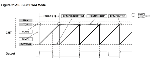
正弦波の下り坂でノイズが入っています。
つまり、TCB0.CCMPH を減らしたときです。
いろいろ想像して、確認して、原因がわかりました。
簡単にいうと、、、
ランナー(カウンタ)が、ゴール(TCB0.CCMPH)に向かって走っているときに、ゴールが先になる場合(TCB0.CCMPHが増える場合)は問題なし。
ゴールした後に変更しても、すでに出力はLOWになっているので大きな問題はない。
だけど、ゴール(TCB0.CCMPH)が手前に来る場合(TCB0.CCMPHが減る場合)は注意。
ゴールした後(カウンタがTCB0.CCMPHを過ぎた後)にゴールを変更しても出力はLOWのままで問題なし。
あるいは、走者がゴールする前で、変更後のゴールも走者の前のときもHIGHのままで問題なし。
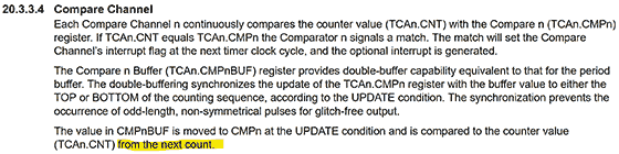
問題なのは、まだ走者がゴールしていないのに(カウンタがTCB0.CCMPHに達していないのに)、走者よりも後ろにゴールを設定してしまったとき(TCB0.CCMPHをカウンタよりも少ない値にしたとき)です。出力がHIGHのまま、カウンタはTOP値まで行ってしまいます。
ということで正弦波のとき限定のパッチを当ててみました。
なぜ正弦波限定なのかというと、正弦波は連続性があり前の値と大きく変わることがない(と思われる)からです。(高い音だとサンプリングの関係で値がとぶと思う。)
新しいループに入ったときに、ゴールの変更はすぐにでもできるのですが、ゴールが近い(TCB0.CCMPHの値が小さい)ときは、上記の事故がおこりうるので、ゴールした後(カウンタがTCB0.CCMPHを過ぎた後)にゴールを変更(TCB0.CCMPHを変更)すればいいということで、適当にウェイトをいれてみたところノイズのない正弦波になりました。
TCB0.CCMPHの更新タイミングが、カウンタが0になったときではなく、即時行われるので起こる事故(ノイズ)だったようです。
原因はわかりましたが、一般的な解決法はまだ思いつきません。
202duinoで正弦波 → ノイズがのる → ATtiny412でDAC使用:放課後マイコンクラブ:SSブログ
https://hello-world.blog.ss-blog.jp/2023-06-10
というので、PWMでの疑似DACをあきらめ、1シリーズのDACでしのぎましたが、こちらの方もATtiny202のPWMでノイズが出たというのを確認しました。
ATtiny202で正弦波を作ったらノイズが入る
https://www.jh4vaj.com/archives/39505
正弦波の下り坂でノイズが入っています。
つまり、TCB0.CCMPH を減らしたときです。
いろいろ想像して、確認して、原因がわかりました。
簡単にいうと、、、
ランナー(カウンタ)が、ゴール(TCB0.CCMPH)に向かって走っているときに、ゴールが先になる場合(TCB0.CCMPHが増える場合)は問題なし。
ゴールした後に変更しても、すでに出力はLOWになっているので大きな問題はない。
だけど、ゴール(TCB0.CCMPH)が手前に来る場合(TCB0.CCMPHが減る場合)は注意。
ゴールした後(カウンタがTCB0.CCMPHを過ぎた後)にゴールを変更しても出力はLOWのままで問題なし。
あるいは、走者がゴールする前で、変更後のゴールも走者の前のときもHIGHのままで問題なし。
問題なのは、まだ走者がゴールしていないのに(カウンタがTCB0.CCMPHに達していないのに)、走者よりも後ろにゴールを設定してしまったとき(TCB0.CCMPHをカウンタよりも少ない値にしたとき)です。出力がHIGHのまま、カウンタはTOP値まで行ってしまいます。
ということで正弦波のとき限定のパッチを当ててみました。
なぜ正弦波限定なのかというと、正弦波は連続性があり前の値と大きく変わることがない(と思われる)からです。(高い音だとサンプリングの関係で値がとぶと思う。)
新しいループに入ったときに、ゴールの変更はすぐにでもできるのですが、ゴールが近い(TCB0.CCMPHの値が小さい)ときは、上記の事故がおこりうるので、ゴールした後(カウンタがTCB0.CCMPHを過ぎた後)にゴールを変更(TCB0.CCMPHを変更)すればいいということで、適当にウェイトをいれてみたところノイズのない正弦波になりました。
TCB0.CCMPHの更新タイミングが、カウンタが0になったときではなく、即時行われるので起こる事故(ノイズ)だったようです。
原因はわかりましたが、一般的な解決法はまだ思いつきません。
//  megaTinyCore ATtiny202/212/402/412 Sine Wave - PWM version
#include <util/delay_basic.h>

static const uint16_t OCTAVE9[] = { 7023, 7441, 7883, 8352, 8848, 9375, 9932, 10523,11148,11811,12513,13258 };
static const uint8_t  SINE256[] = {
    0,  0,  0,  0,  1,  1,  1,  2,  2,  3,  4,  5,  5,  6,  7,  9,  10, 11, 12, 14, 15, 17, 18, 20, 21, 23, 25, 27, 29, 31, 33, 35,
   37, 40, 42, 44, 47, 49, 52, 54, 57, 59, 62, 65, 67, 70, 73, 76,  79, 82, 85, 88, 90, 93, 97,100,103,106,109,112,115,118,121,124,
  128,131,134,137,140,143,146,149,152,155,158,162,165,167,170,173, 176,179,182,185,188,190,193,196,198,201,203,206,208,211,213,215,
  218,220,222,224,226,228,230,232,234,235,237,238,240,241,243,244, 245,246,248,249,250,250,251,252,253,253,254,254,254,255,255,255,
  255,255,255,255,254,254,254,253,253,252,251,250,250,249,248,246, 245,244,243,241,240,238,237,235,234,232,230,228,226,224,222,220,
  218,215,213,211,208,206,203,201,198,196,193,190,188,185,182,179, 176,173,170,167,165,162,158,155,152,149,146,143,140,137,134,131,
  128,124,121,118,115,112,109,106,103,100, 97, 93, 90, 88, 85, 82,  79, 76, 73, 70, 67, 65, 62, 59, 57, 54, 52, 49, 47, 44, 42, 40,
   37, 35, 33, 31, 29, 27, 25, 23, 21, 20, 18, 17, 15, 14, 12, 11,  10,  9,  7,  6,  5,  5,  4,  3,  2,  2,  1,  1,  1,  0,  0,  0 };

void setup(){                   // Register Settings
  TCB0.CTRLA = TCB_CLKSEL_CLKDIV1_gc | TCB_ENABLE_bm;   // 20MHz / 1 / 256 -> 78,125Hz
  TCB0.CTRLB = TCB_CNTMODE_PWM8_gc   | TCB_CCMPEN_bm;   // 8-Bit PWM mode, Output Enable (WO,PA6,megaTinyCore:P0)
  TCB0.CCMPL = 0xff;                                    // top value = 255
  TCB0.CCMPH = 0;                                       // output value
}

void loop(){
  sineWave( 60,  500);          // C4
  sineWave( 64,  500);          // E4
  sineWave( 67,  500);          // G4
  sineWave( 72, 2000);          // C5
  delay(1000);
}

void sineWave(uint8_t midiNum, uint16_t msDuration) {
  uint16_t i, di = OCTAVE9[ midiNum % 12 ] >> (10 - midiNum / 12);  // 256 times the Wave Table subscript to advance in one cycle
  uint32_t cycDuration = F_CPU / 256 / 1000 * msDuration;           // Convert duration to number of cycles
  static uint8_t pwNew, pwNow;
  do {
    pwNew = SINE256[ ( (i += di) >> 8 ) ];
    if( pwNew < pwNow && pwNow <120) _delay_loop_1(40); // <== Noise Reduction (wait 3x40=120cycle)
    TCB0.CCMPH = pwNow = pwNew;                         // 8bit PWM (78,125Hz)
    while( !TCB0.INTFLAGS );                            // Waiting for TCB0 overflow (every 12.8usec(78,125Hz))
    TCB0.INTFLAGS = TCB_CAPT_bm;                        // cleared by writing a '1'
  } while( --cycDuration );                             // Exit if note data is 0
  TCB0.CCMPH = 0;                                       // Set output to 0
}
202duino の SPI で NeoPixel [Arduino]
NTSCビデオ信号のドット幅がなかなかそろわず、SPIに手を出そうと、、。
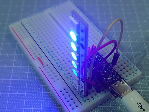
SPIでデータを送る練習としてNeoPixelで実験。
以前に作ったのと同様にNeoPixel棒を光らせられました。
202duino で NeoPixel [Arduino]
https://hello-world.blog.ss-blog.jp/2023-07-15
スケッチサイズは582バイトと軽量に。
WS2812Bのデータシートには、
Data transfar Time
0 : High 220- 380ns / Low 580-1000ns
1 : High 580-1000ns / Low 580-1000ns
ってあるけと、どうやら Highの時間の長短で0/1を決めているみたいで、Lowの時間は厳密に守らなくてもいいみたい。
問題点は、ATtiny202は実質の有効ピンが5ピンにも関わらず、SPIを使うと、MOSIの他、MISO、SCK も使ってしまうので、他に使える残りのピンが2本になってしまい、あまり実用的ではないかも。
というわけで、NTSCビデオ計画はちょっと保留。
SPIでデータを送る練習としてNeoPixelで実験。
以前に作ったのと同様にNeoPixel棒を光らせられました。
202duino で NeoPixel [Arduino]
https://hello-world.blog.ss-blog.jp/2023-07-15
スケッチサイズは582バイトと軽量に。
// ATtiny202 SPI NeoPixel test (20MHz)

#define T0        (0b11100000)  // T0H : 300ns @ 20MHz CLK2X DIV4
#define T1        (0b11111100)  // T1H : 600ns @ 20MHz CLK2X DIV4
#define NUMPIXELS (12)

uint8_t pixels[NUMPIXELS * 3];  // GRBGRBGRB...

void setup() {
  PORTA.DIRSET = _BV(1);        // PA1(MOSI) OUTPUT (megaTinyCore:D2)
  SPI0.CTRLA   = SPI_MASTER_bm | SPI_CLK2X_bm | SPI_PRESC_DIV4_gc | SPI_ENABLE_bm;
  SPI0.CTRLB   = SPI_BUFEN_bm | SPI_BUFWR_bm | SPI_SSD_bm | SPI_MODE_1_gc;
}

void loop() {
  for (uint8_t i = 0; i < NUMPIXELS; i++) {
    for (uint8_t c = 0; c < 6; c++) {
        pixels[ ((NUMPIXELS + i - c) * 3 + 2) % (NUMPIXELS * 3) ] = 31 >> c;
    }
    neoPixelShow();
    delay(100);
  }
}

void neoPixelShow() {
  for(uint8_t i = 0; i < NUMPIXELS * 3; i++) {
    for(uint8_t bm = 0b10000000; bm; bm >>= 1) {
      SPI0.DATA = (pixels[i] & bm) ? T1 : T0;
      while( !(SPI0.INTFLAGS & SPI_DREIF_bm) );
    }
  }
}
WS2812Bのデータシートには、
Data transfar Time
0 : High 220- 380ns / Low 580-1000ns
1 : High 580-1000ns / Low 580-1000ns
ってあるけと、どうやら Highの時間の長短で0/1を決めているみたいで、Lowの時間は厳密に守らなくてもいいみたい。
問題点は、ATtiny202は実質の有効ピンが5ピンにも関わらず、SPIを使うと、MOSIの他、MISO、SCK も使ってしまうので、他に使える残りのピンが2本になってしまい、あまり実用的ではないかも。
というわけで、NTSCビデオ計画はちょっと保留。


