前の10件 | -
AtomS3 Liteで赤外線リモコン [Arduino]
AtomS3 Liteには赤外線LEDが付いていて、サンプルにもNECタイプのリモコンスケッチがあった。
でも、うちのテレビはソニー製。うちのソニーのテレビリモコンは電源ボタン以外は赤外線ではないものの、テレビ本体は赤外線リモコンの受信は可能。
というわけで、サンプルスケッチをいじってソニーのテレビの操作。
といってもボタンも1つしかないので単機能、ミュートのトグル。
それにしても、うちの遅いパソコンではコンパイルに時間がかかる。
調べてみると、ESP32は簡単にPWMをつくることができるようだ。
というわけでリモコン信号も簡単にできた。
ライブラリ不要となり、多少コンパイル時間も短くなり、プログラムのサイズも減った。
AtomS3 Liteの赤外線LEDが光っている様子。
でも、うちのテレビはソニー製。うちのソニーのテレビリモコンは電源ボタン以外は赤外線ではないものの、テレビ本体は赤外線リモコンの受信は可能。
というわけで、サンプルスケッチをいじってソニーのテレビの操作。
といってもボタンも1つしかないので単機能、ミュートのトグル。
// Infrared remote control  (M5atomS3, SIRC version)
#define DISABLE_CODE_FOR_RECEIVER
#define SEND_PWM_BY_TIMER                       // use hardware PWM
#define IR_TX_PIN 4
#include "M5AtomS3.h"
#include <IRremote.hpp>

void setup() {
    auto cfg = M5.config();
    AtomS3.begin(cfg);
    IrSender.begin(DISABLE_LED_FEEDBACK);       // Start with IR_SEND_PIN as send pin
    IrSender.setSendPin(IR_TX_PIN);
}

void loop() {
    AtomS3.update();
    if( AtomS3.BtnA.wasPressed() ) {
        IrSender.sendSony( 0x01, 0x14, 3, SIRCS_12_PROTOCOL );  // SONY TV mute toggle
    }   // address:0x01(TV,5bits), command:0x14(mute,7bits), repeat:3times, 12bits
}
それにしても、うちの遅いパソコンではコンパイルに時間がかかる。
調べてみると、ESP32は簡単にPWMをつくることができるようだ。
というわけでリモコン信号も簡単にできた。
// Infrared remote control with 40kHz PWM (ESP32, SIRC version)
uint8_t ledIR = 4;

void setup() {
  ledcSetup( 1, 40000, 8 );             // 40 kHz PWM, 8-bit resolution
  ledcAttachPin( ledIR, 1 );            // assign IR LED pin to channel
  pinMode( 41, INPUT_PULLUP );
}

void loop() {
  while( digitalRead( 41 ) );
  sendIrSIRCesp32( 0x14 | 0x01 << 7 );  // SONY mute toggle (cmd:0x14(7bit), adrs:0x01(5bit))
  sendIrSIRCesp32( 0x14 | 0x01 << 7 );  //   repeat 3 times
  sendIrSIRCesp32( 0x14 | 0x01 << 7 );
}

void sendIrSIRCesp32( uint32_t d ) {                    //   T = 0.60msec
  uint8_t  b = (d & 0xF8000) ? 20 :
               (d & 0x07000) ? 15 : 12;                 // number of bits
  uint16_t usON, usTrailer = 42000;                     // 70T = interval(75T) - leader(5T)
  ledcWrite( 1, 85 ); delayMicroseconds( 2400 );        // leader ON  (4T)
  ledcWrite( 1,  0 ); delayMicroseconds(  600 );        // leader OFF (1T)
  for(uint8_t i = 0; i < b; i++) {                      // data(command + address)
    usON = ((d>>i)&1) ? 1200 : 600;                     // data(0:1T / 1:2T)
    ledcWrite( 1, 85 ); delayMicroseconds( usON );      // data ON
    ledcWrite( 1,  0 ); delayMicroseconds(  600 );      // data OFF (1T)
    usTrailer -= (usON + 600);                          // trailer
  }
  delayMicroseconds( usTrailer );
}
ライブラリ不要となり、多少コンパイル時間も短くなり、プログラムのサイズも減った。
AtomS3 Liteの赤外線LEDが光っている様子。
AtomS3 Lite 買ってみた。 [Arduino]
無線(というかWi-Fi)を使ってみたくてちょっと調べてみた。
・Uno R4 WiFi でもいいんだけど、、小さいやつ希望
・type-Cで
・技適通ってるやつで
・DIPの幅狭めで
・新しめで
・情報多めのやつで
Nano ESP32 | Arduino Documentation
https://docs.arduino.cc/hardware/nano-esp32
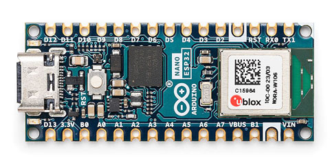
「Arduino Nano ESP32」がtype-CでArduino純正のボードだけど、技適通ってないっぽい。
Seeed Studio XIAO ESP32S3 — スイッチサイエンス
https://www.switch-science.com/products/8968
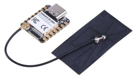
同じESP32S3使ってる「Seeed Studio XIAO ESP32S3」もいいけど、アンテナが外付け&本体よりでかい。
ESP32-C3 か S3 かどっちがいいのかもよくわからない。
UNO R4 WiFi や nano ESP32 には S3 が載っているので、とりあえず S3 の方向で。
ほかにESP32S3で探すと、M5Stack関連が出てきた。
M5Stackというとディスプレイとかボタンとかいろいろ付いている系と思っていたけど、割とシンプルなボードもあったので購入してみた。
AtomS3 Lite
https://docs.m5stack.com/en/core/AtomS3%20Lite
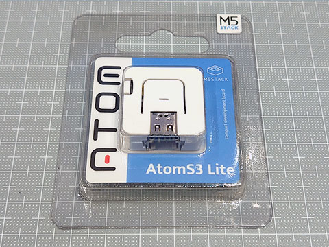
AtomS3 Lite:ボタン、RGB LED、赤外線LEDが付いている。
M5StampS3 PIN2.54
https://docs.m5stack.com/en/core/M5StampS3%20PIN2.54
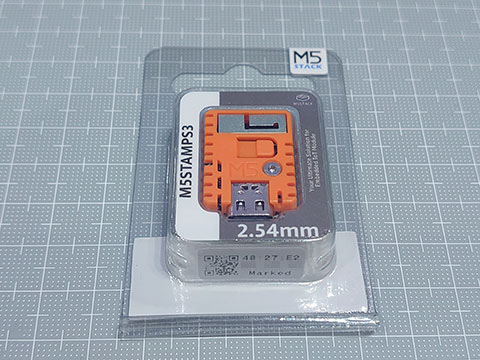
M5stampS3:ボタン、RGB LEDだけ。ブレッドボードで遊べるように2.54mm DIPタイプを選択。
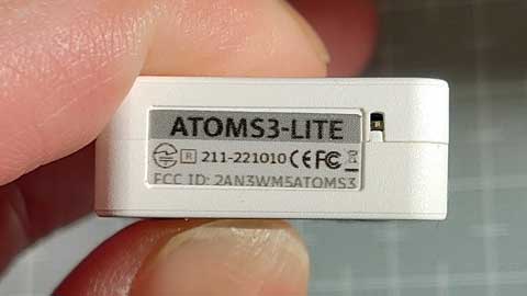
とりあえず、AtomS3 Liteを開封
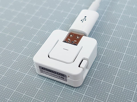
技適通ってる。
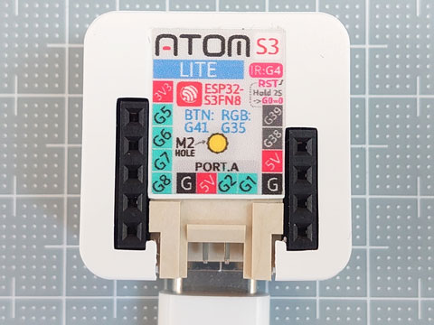
裸眼では読めない部分あり。
・Uno R4 WiFi でもいいんだけど、、小さいやつ希望
・type-Cで
・技適通ってるやつで
・DIPの幅狭めで
・新しめで
・情報多めのやつで
Nano ESP32 | Arduino Documentation
https://docs.arduino.cc/hardware/nano-esp32
「Arduino Nano ESP32」がtype-CでArduino純正のボードだけど、技適通ってないっぽい。
Seeed Studio XIAO ESP32S3 — スイッチサイエンス
https://www.switch-science.com/products/8968
同じESP32S3使ってる「Seeed Studio XIAO ESP32S3」もいいけど、アンテナが外付け&本体よりでかい。
ESP32-C3 か S3 かどっちがいいのかもよくわからない。
UNO R4 WiFi や nano ESP32 には S3 が載っているので、とりあえず S3 の方向で。
ほかにESP32S3で探すと、M5Stack関連が出てきた。
M5Stackというとディスプレイとかボタンとかいろいろ付いている系と思っていたけど、割とシンプルなボードもあったので購入してみた。
AtomS3 Lite
https://docs.m5stack.com/en/core/AtomS3%20Lite
AtomS3 Lite:ボタン、RGB LED、赤外線LEDが付いている。
M5StampS3 PIN2.54
https://docs.m5stack.com/en/core/M5StampS3%20PIN2.54
M5stampS3:ボタン、RGB LEDだけ。ブレッドボードで遊べるように2.54mm DIPタイプを選択。
とりあえず、AtomS3 Liteを開封
技適通ってる。
裸眼では読めない部分あり。
![M5Stack ATOMS3 Lite【M5STACK-C124】[エムファイブスタック マイコン IoT モジュール 電子工作 自由工作]](https://thumbnail.image.rakuten.co.jp/@0_mall/marutsuelec/cabinet/04881820/230620/2719675_2.jpg?_ex=128x128 "M5Stack ATOMS3 Lite【M5STACK-C124】[エムファイブスタック マイコン IoT モジュール 電子工作 自由工作]")
UNO R4で音楽演奏 [Arduino]
音楽演奏のスケッチをいろいろなバージョンで作ってきたけど、UNO R4でもやってみた。
・DAC(12bit)を使用
・正弦波は計算で作成
・音程も計算で作成
・レジスタ触らない
・ところどころブラッシュアップ
10kΩの可変抵抗の前に100kΩの抵抗を挟んで約10分の1に分圧したらボリュームとしてちょうどいい感じ。(理論上は40kΩかな)
楽譜の作成と定義のファイルは以前と同様。
https://hello-world.blog.ss-blog.jp/2022-07-04
・DAC(12bit)を使用
・正弦波は計算で作成
・音程も計算で作成
・レジスタ触らない
・ところどころブラッシュアップ
10kΩの可変抵抗の前に100kΩの抵抗を挟んで約10分の1に分圧したらボリュームとしてちょうどいい感じ。(理論上は40kΩかな)
楽譜の作成と定義のファイルは以前と同様。
https://hello-world.blog.ss-blog.jp/2022-07-04
// Uno R4 DAC Score Replay Sketch
#include "notes2.h"                     // note definition data (pitch(octave,scale) + length)
#define F_SAMP      50000               // sampling frequency (Hz) (divisor of 1,000,000 (usec))
#define MAX_TRACK   4                   // Maximum tracks
static uint16_t   SIN[256];             // array of sine wave
static uint16_t   OCT9[12];             // array subscript difference in the 9th octave
static const uint16_t Jesus[] = {       // J.S.Bach "Jesu, Joy of Man's Desiring"
  125 , 0 ,
  b4e , g4e , a4e , b4e , d5e , c5e , c5e , e5e , d5e , d5e , g5e , F5e , g5e , d5e , b4e , g4e , a4e , b4e ,
  e4e , d5e , c5e , b4e , a4e , g4e , d4e , g4e , F4e , g4e , b4e , d5e , g5hd,                           0 ,
  d4q       , F4e , g4q       , F4e , g4q       , a4e , b4q       , a4e , b4q       , g4e , e4q       , g4e ,
  a4q       , F4e , g4q       , e4e , a3q       , c4e , b3w ,                                             0 ,
  g3qd            , e3qd            , c3qd            , b2qd            , e3qd            , d3qd            ,
  c3qd            , C3qd            , d3qd            , g2w ,                                             0 , 0 };

void setup(){
  uint16_t  i;
  analogWriteResolution(12);
  for(i=0; i<256; i++)  SIN[i]  = 16383.9 * (1 - cos(6.283185 * i / 256)) / 2;      // 14bit sine wave
  for(i=0; i< 12; i++)  OCT9[i] = (440 << 16) * pow(2, (i + 51) / 12.0) / F_SAMP;   // A4=440
}

void loop(){
  playR4( Jesus );
}

void playR4( const uint16_t *score ){
  uint8_t  Tracks = 0;                  // track count
  uint16_t note;                        // note (pitch(octave,scale) + length)
  uint16_t NoteCycle, n;                // reference note (96th note) cycle and its counter (n)
  uint16_t   p[MAX_TRACK];              // pointer for each track
  uint8_t  len[MAX_TRACK];              // note length (how many 96th notes)
  uint16_t   s[MAX_TRACK] = {0};        // waveform subscript  (s)  (x256)
  uint16_t  ds[MAX_TRACK] = {0};        //  and its difference (ds) (x256)
  uint16_t env[MAX_TRACK];              // sound envelope
  uint16_t atn = 0, Atn;                // attenuation counter and initial value
  // *** Preparing Scores ***
  Atn = 150 * F_SAMP / 1000 / 356;                  // attenuation half-life : 150 msec
  NoteCycle = F_SAMP *4*60 / score[0] / MIN_NOTE;   // reference note(96th note) cycles
  for( uint16_t i = 1; Tracks < MAX_TRACK; ) {      // Get track count and starting location
    if( score[i++] != 0 ) continue;     // Skip until 0 comes
    if( score[i]   == 0 ) break;        // If two 0s follow, end of data
    len[ Tracks ] = 1;                  // note length subtraction counter to 1
    p[ Tracks++ ] = i;                  // Get location in memory, Count up the tracks
  }
  // *** Playback ***
  n = Tracks;                           // To play immediately after the loop starts
  uint32_t  usInt = 1000000 / F_SAMP;   // sampling time interval(usec)
  uint32_t  usPre = micros();           // sampling time previous value(usec)
  do {
    if( --n < Tracks ) {                // Processing of score for each reference note length
      if( !--len[n] ) {
        note   = score[ p[n]++ ];
        len[n] = note & 0x00ff;         // The lower 8 bits are note length (Multiples of 96th notes)
        if( note & 0xff00 ) {           // If not a rest... (Leave a lingering sound even with rests)
           ds[n] = OCT9[ (note>>8) & 0x0f ] >> (9 - (note>>12));    // increment subscript (x256)
            s[n] = 0;                   // start of waveform cycle
          env[n] = 0xffff;              // the maximum amplitude initially
        }
      }
      if( !n ) n = NoteCycle;
    }
    switch( Tracks ) {                  // Change output by number of tracks
      case 1: analogWrite( DAC, ( SIN[ (s[0]+=ds[0])>>8 ] * env[0] ) >> 18 );  // 14x16=30bit >> 18 = 12bit
              break;
      case 2: analogWrite( DAC, ( SIN[ (s[0]+=ds[0])>>8 ] * env[0]
                                + SIN[ (s[1]+=ds[1])>>8 ] * env[1] ) >> 19 );  // 30/30(31bit)
              break;
      case 3: analogWrite( DAC, ( SIN[ (s[0]+=ds[0])>>8 ] * env[0]
                                + SIN[ (s[1]+=ds[1])>>8 ] * env[1]
                                + SIN[ (s[2]+=ds[2])>>8 ] * env[2] ) >> 20 );  // 30/30/30(31.5bit)
              break;
      case 4: analogWrite( DAC, ( SIN[ (s[0]+=ds[0])>>8 ] * env[0]
                                + SIN[ (s[1]+=ds[1])>>8 ] * env[1]
                                + SIN[ (s[2]+=ds[2])>>8 ] * env[2]
                                + SIN[ (s[3]+=ds[3])>>8 ] * env[3] ) >> 20 );  // 30/30/30/30(32bit)
    }
    if( !atn-- )            atn   = Atn;            // subtract attenuation counter
    if(  atn < Tracks ) env[atn] -= (env[atn]>>9);  // amplitude attenuation
    while( micros() - usPre < usInt );              // wait for next cycle
    usPre += usInt;
  } while( note );                      // Exit if note data is 0
  analogWrite( DAC, 0 );                // Set output to 0
}
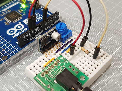
オーディオアンプモジュール いろいろ [Arduino]
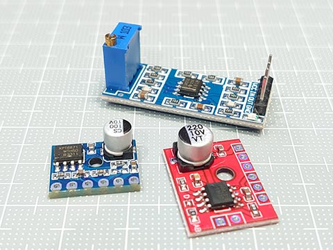
オーディオアンプモジュールを3種類購入してみた。
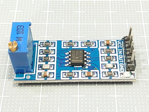
LM358というのを使ったモジュール。
使い方がわからなかった。
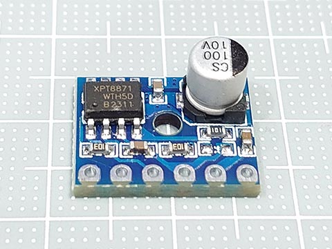
HAA2018というを使ったモジュール。(販売元の説明ではXS9871であった。)
muteがHIGHのときミュートになるらしいが、デフォルトではGNDにつながっていないのに音が出た。muteに5Vかけたらミュートになった。
UNO R4のA0のDACからの電圧を可変抵抗でだいぶ落とさないと音が割れた。
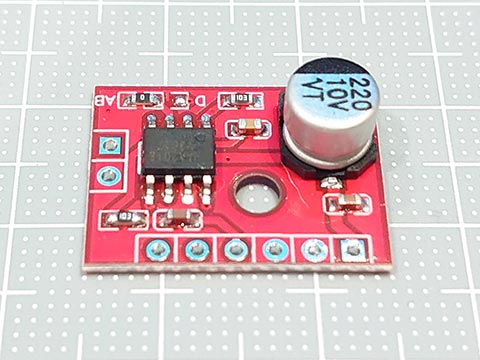
XPT8871というを使ったモジュール。(販売元の写真ではLTK5128のやつもあった。)
こっちはmuteをGNDに落とさないと音が出なかった。
これも可変抵抗で電圧を落として入力。
裏面に各ピンの説明がシルク印刷されていて、普通のヘッダーピンだと見えなくなるので、L字のものを使ってみた。
ちょっと調べてみると、ライン入力は1Vっぽいので、5VのUNO R4の場合、可変抵抗に入力する前に、その4倍以上の抵抗を挟まないといけなさそう。
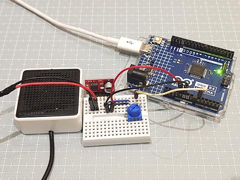
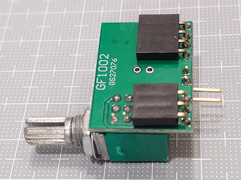
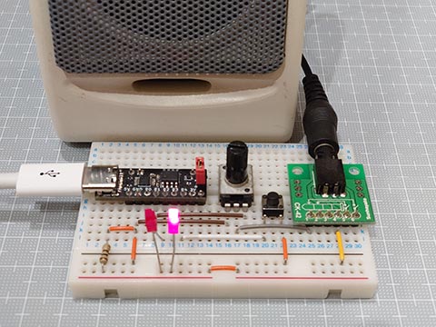
オーディオアンプモジュール GF1002 [Arduino]
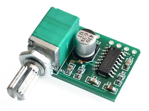
PAM8403を搭載したアンプモジュール。
amazon や Aliexpress でよく見かけるやつ。
可変抵抗もついてて便利そうなんだけど、これの問題は、スルーホールのピッチが微妙なところ。
入力部、電源部、出力部のそれぞれの内部は2.54mmピッチだけど、パート間のピッチは2.54mmピッチとは全く異なりブレッドボードに載らない、、。
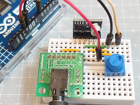
そこで、ちょっと考えた。
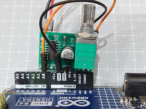
・電源だけピンを立てる
・それ以外はソケットに
・Arduinoの電源に直刺しのとき、モジュールの基盤が邪魔にならないようL字ピン
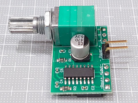
(電源のGNDとオーディオのGNDをつなげておいてもいいと思う)
これをArduino UNO R4に載せてみる。
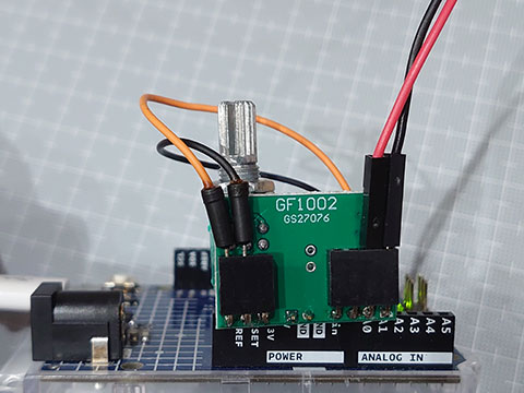
ちょっとしたDACからの音声テストには便利。
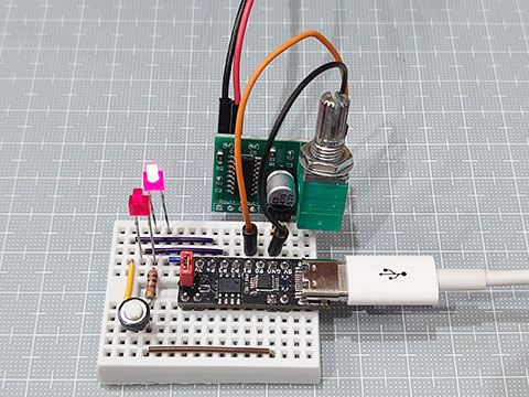
ブレッドボートでもOK。

VKLSVAN 5個 PAM8403 2X3Wミニ 5V デジタル アンプ基板 USB 電源 オーディオ アンプ モジュール
- 出版社/メーカー: VKLSVAN
- メディア:
踏切警報音 UNO R4 [Arduino]
踏切警報音スケッチをUNO R4用にも作ってみた。
UNO R4にはDACがあるのと、速度も速いので、レジスタ操作なしの純粋Arduinoでいけた。
量子化ビット数は DACの12ビット。
micros()でタイミングをとっているので、サンプリング周波数は 1,000,000(μsec)の約数。そのなかで処理が間に合う最大の50kHzとした。
UNO R4はAVRマイコンに比べてドライブ能力が低いので、アンプを使わないとそこそこの音量が出ないのが難点。
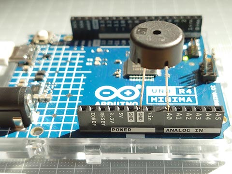
とりあえず圧電サウンダで。
UNO R4にはDACがあるのと、速度も速いので、レジスタ操作なしの純粋Arduinoでいけた。
量子化ビット数は DACの12ビット。
micros()でタイミングをとっているので、サンプリング周波数は 1,000,000(μsec)の約数。そのなかで処理が間に合う最大の50kHzとした。
UNO R4はAVRマイコンに比べてドライブ能力が低いので、アンプを使わないとそこそこの音量が出ないのが難点。
とりあえず圧電サウンダで。
// railroad crossing sounds and signals : UNO R4
#define F_SAMP    50000         // sampling frequency (Hz) (divisor of 1,000,000 (usec))
#define F_SIGN    100           // light signal : 100/min  (1.666Hz, 0.6  sec)
#define F_DING    130           // ding sound   : 130/min  (2.166Hz, 0.461sec)
#define ATHALF    200           // attenuation half-life : 200 msec
static const uint16_t FRQ[][2] = {      // frequency combination (Hz)
      { 700,  750 },            // JR etc.
      { 450,  550 },            // ODAKYU
      { 550,  650 },            // TOKYU, KEIKYU
      { 600,  650 },            // TOBU
      { 520,  660 }             // SEIBU
};
static uint16_t  SIN[256];      // array of sine wave

void setup() {
  analogWriteResolution(12);    // A0 : DAC
  pinMode( A1, OUTPUT );        // A1 : LED1
  pinMode( A2, OUTPUT );        // A2 : LED2
  pinMode( A3, INPUT_PULLUP );  // A3 : SW
  for (uint16_t i = 0; i < 256; i++) {
    SIN[i] = 32767.9 * (1 - cos(6.283185 * i / 256)) / 2;       // 15bit
  }
}

void loop() {
  static uint8_t ch;
  uint16_t  cDing, iDing = 60 * F_SAMP / F_DING;        // counter and initial cycles of ding sound
  uint16_t  cSign, iSign = 60 * F_SAMP / F_SIGN;        // counter and initial cycles of lignt signal
  uint16_t  cAttn, iAttn = ATHALF * F_SAMP /1000 /356;  // counter and initial cycles of attenuation
  uint16_t  iA, diA = (FRQ[ch][0] << 16) / F_SAMP;      // array subscript and its difference
  uint16_t  iB, diB = (FRQ[ch][1] << 16) / F_SAMP;
  uint16_t  env;                                        // envelope
  uint32_t  usInt = 1000000 / F_SAMP;                   // sampling time interval(usec)
  uint32_t  usPre = micros();                           // sampling time previous value(usec)
  digitalWrite( A1, HIGH );     // LED1 On
  digitalWrite( A2, LOW  );     // LED2 Off
  cDing = cSign= 0;
  do {
    if( !cDing-- ) {            // reset ding counter
      cDing = iDing;
      cAttn = iAttn;
      env   = 0xffff;
      iA    = 0;
      iB    = 0;
    }
    if( !cAttn-- ) {            // reset attenuation counter
      cAttn = iAttn;
      env  -= env >> 9;
    }
    if( !cSign-- ) {            // reset light counter
      cSign = iSign;
      digitalWrite( A1, !digitalRead(A1) );
      digitalWrite( A2, !digitalRead(A2) );
    }
    analogWrite( DAC, (SIN[(iA+=diA)>>8] + SIN[(iB+=diB)>>8]) * env >> 20 );
    while( micros() - usPre < usInt );
    usPre += usInt;
  } while( digitalRead(A3) );   // Press the tact switch to end
  analogWrite( DAC, 0 );
  digitalWrite( A1, LOW  );     // LED1 Off
  digitalWrite( A2, LOW  );     // LED2 Off
  delay(1000);
  if( ++ch == sizeof(FRQ)/sizeof(*FRQ) ) ch = 0;
}
踏切警報音 リトライ [Arduino]
以前にも踏切の音を出してみるのをやったけど、もうちょっとリアルに。
以下から情報をいただきました。感謝。
【参考にさせていただいたところ】
Web Nucky Blog |踏切警報音の実験 その1
https://webnucky.blog.fc2.com/blog-entry-296.html
踏切警報音 - くるまや軽便鉄道 PartⅡ
https://kurumayakeiben.wordpress.com/category/%E8%B8%8F%E5%88%87%E8%AD%A6%E5%A0%B1%E9%9F%B3/
鉄道マニヤに捧ぐ 首都圏主要鉄道会社の踏切音に使用される微分音:左近治の囈(たはごと):SSブログ
https://tawauwagotsakonosamu.blog.ss-blog.jp/2019-09-19
★いきなりまとめ
・本物の踏切の音と光は安全のため別回路になっていて、同期していない。
・現在の電子ホーン式のほかに電鈴式、電鐘式がある。
・音は2(~3(京急))和音で、12音階に属さない「微分音」というものらしい。
JR、相鉄、名鉄、京阪、近鉄、阪神、西鉄、阪急、南海、京成 他 700Hz、750Hz
小田急 450Hz、550Hz
東急、京急 550Hz、650Hz
東武 600Hz、650Hz
西武 520Hz、660Hz
★スケッチの方向性
・ATtiny202 (megaTinyCore) を使う
・TCA0のPWMをDACもどきとして使用 (mills(), micros()や他のPWMは使用不可)
・電子ホーン式のみ
・CPU周波数に依存しない
スケッチつくったけど、半分くらいが初期値の設定やレジスタ設定や正弦波の配列などで埋まりました。
音の周波数の組み合わせを選択できるようにした。
音のリズムはとりあえず130/分にしたけど変更可能。
正弦波、鋸歯状波、矩形波を試してみたけど、正弦波が一番近いかな?
踏切の動画をミュートで見ながら、手元で音を出しても違和感なし。
小さいスピーカより大きめのスピーカのほうがいい音が出た。
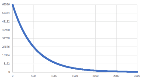
音の減衰具合。半分の値になるのが、356cyclesくらい。
以下から情報をいただきました。感謝。
【参考にさせていただいたところ】
Web Nucky Blog |踏切警報音の実験 その1
https://webnucky.blog.fc2.com/blog-entry-296.html
踏切警報音 - くるまや軽便鉄道 PartⅡ
https://kurumayakeiben.wordpress.com/category/%E8%B8%8F%E5%88%87%E8%AD%A6%E5%A0%B1%E9%9F%B3/
鉄道マニヤに捧ぐ 首都圏主要鉄道会社の踏切音に使用される微分音:左近治の囈(たはごと):SSブログ
https://tawauwagotsakonosamu.blog.ss-blog.jp/2019-09-19
★いきなりまとめ
・本物の踏切の音と光は安全のため別回路になっていて、同期していない。
・現在の電子ホーン式のほかに電鈴式、電鐘式がある。
・音は2(~3(京急))和音で、12音階に属さない「微分音」というものらしい。
JR、相鉄、名鉄、京阪、近鉄、阪神、西鉄、阪急、南海、京成 他 700Hz、750Hz
小田急 450Hz、550Hz
東急、京急 550Hz、650Hz
東武 600Hz、650Hz
西武 520Hz、660Hz
★スケッチの方向性
・ATtiny202 (megaTinyCore) を使う
・TCA0のPWMをDACもどきとして使用 (mills(), micros()や他のPWMは使用不可)
・電子ホーン式のみ
・CPU周波数に依存しない
スケッチつくったけど、半分くらいが初期値の設定やレジスタ設定や正弦波の配列などで埋まりました。
音の周波数の組み合わせを選択できるようにした。
音のリズムはとりあえず130/分にしたけど変更可能。
正弦波、鋸歯状波、矩形波を試してみたけど、正弦波が一番近いかな?
踏切の動画をミュートで見ながら、手元で音を出しても違和感なし。
// railroad crossing sound and signals : ATtiny202 (megaTinyCore 4-20MHz)
#include <util/delay.h>
#define F_SIGN    100           // light signal : 100/min (1.666Hz, 0.6  sec)
#define F_DING    130           // ding sound   : 130/min (2.166Hz, 0.461sec)
#define ATHALF    200           // attenuation half-life : 200 msec
static const uint16_t FRQ[][2] = {              // frequency combination (Hz)
      { 750,  700 },            // JR, SOTETSU, MEITETSU, KEIHAN, KINTETSU, HANSHIN, NISHITETSU, HANKYU, NANKAI, KEISEI..
      { 450,  550 },            // ODAKYU
      { 550,  650 },            // TOKYU, KEIKYU
      { 600,  650 },            // TOBU
      { 520,  660 }             // SEIBU
};
static const uint8_t  SIN[] = {                 // array of sine wave
    0,  0,  0,  0,  1,  1,  1,  2,  2,  3,  4,  5,  5,  6,  7,  9,  10, 11, 12, 14, 15, 17, 18, 20, 21, 23, 25, 27, 29, 31, 33, 35,
   37, 40, 42, 44, 47, 49, 52, 54, 57, 59, 62, 65, 67, 70, 73, 76,  79, 82, 85, 88, 90, 93, 97,100,103,106,109,112,115,118,121,124,
  128,131,134,137,140,143,146,149,152,155,158,162,165,167,170,173, 176,179,182,185,188,190,193,196,198,201,203,206,208,211,213,215,
  218,220,222,224,226,228,230,232,234,235,237,238,240,241,243,244, 245,246,248,249,250,250,251,252,253,253,254,254,254,255,255,255,
  255,255,255,255,254,254,254,253,253,252,251,250,250,249,248,246, 245,244,243,241,240,238,237,235,234,232,230,228,226,224,222,220,
  218,215,213,211,208,206,203,201,198,196,193,190,188,185,182,179, 176,173,170,167,165,162,158,155,152,149,146,143,140,137,134,131,
  128,124,121,118,115,112,109,106,103,100, 97, 93, 90, 88, 85, 82,  79, 76, 73, 70, 67, 65, 62, 59, 57, 54, 52, 49, 47, 44, 42, 40,
   37, 35, 33, 31, 29, 27, 25, 23, 21, 20, 18, 17, 15, 14, 12, 11,  10,  9,  7,  6,  5,  5,  4,  3,  2,  2,  1,  1,  1,  0,  0,  0
};

void setup() {
  PORTA.DIRSET        = PIN7_bm;                // PA7   SP  OUTPUT (mTC:1) (mTC default : PA3(mTC:4) to PA7(mTC:1) )
  PORTA.DIRSET        = PIN1_bm | PIN2_bm;      // PA1,2 LED OUTPUT (mTC:2,3)
  PORTA.DIRCLR        = PIN3_bm;                // PA3   SW  INPUT  (mTC:4)
  PORTA.PIN3CTRL      = PORT_PULLUPEN_bm;
  TCA0.SINGLE.INTCTRL = 0;                      // turn off Arduino(mTC) time system
  TCA0.SINGLE.CTRLD   = 0;                      // turn off split mode
  TCA0.SINGLE.CTRLC   = 0;                      // PWM output pins override - disable
  TCA0.SINGLE.CTRLB   = TCA_SINGLE_CMP0EN_bm    // enable compare channel 0
                      | TCA_SINGLE_WGMODE_SINGLESLOPE_gc;   // set Single-slope PWM mode
  TCA0.SINGLE.CTRLA   = TCA_SINGLE_CLKSEL_DIV1_gc           // 20MHz / 1 / 256 -> 78,125Hz
                      | TCA_SINGLE_ENABLE_bm;   // start timer
  TCA0.SINGLE.PERBUF  = 0xff;                   // top value = 255
}

void loop() {
  static uint8_t  ch = 0;
  uint16_t  cDing,  iDing = 60 * (F_CPU >> 8) / F_DING;         // counter and initial cycles of ding sound
  uint16_t  cSign,  iSign = 60 * (F_CPU >> 8) / F_SIGN;         // counter and initial cycles of lignt signal
  uint16_t  cAttn,  iAttn = ATHALF * (F_CPU >> 8) / 1000 / 356; // counter and initial cycles of attenuation
  uint16_t  iA, diA = FRQ[ch][0] * 0x010000 / (F_CPU >> 8);     // array subscript and its difference
  uint16_t  iB, diB = FRQ[ch][1] * 0x010000 / (F_CPU >> 8);
  uint16_t  env;                                                // envelope
  PORTA.OUTSET = PIN1_bm;                       // LED On
  PORTA.OUTCLR = PIN2_bm;                       // LED Off
  cDing = cSign= 0;
  do{
    if( !cDing-- ) {                            // reset ding conter
      cAttn = iAttn;  env = 0xffff;   cDing = iDing;
      iA = iB = 0;
    }
    if( !cAttn-- ) {                            // reset attenuation conter
      cAttn = iAttn;  env -= (env>>9);
    }
    if( !cSign-- ) {                            // reset light counter
      cSign = iSign;
      PORTA.OUTTGL = PIN1_bm | PIN2_bm;         // toggle LEDs
    }
    TCA0.SINGLE.CMP0BUF = ( SIN[ (iA+=diA)>>8 ] + SIN[ (iB+=diB)>>8 ] ) * (env>>9) >>8;
    while( !(TCA0.SINGLE.INTFLAGS & TCA_SINGLE_OVF_bm) );       // Waiting for TCA0 overflow
    TCA0.SINGLE.INTFLAGS = TCA_SINGLE_OVF_bm;   // cleared by writing a '1'
  } while( (PORTA.IN & PIN3_bm) );
  PORTA.OUTCLR = PIN1_bm | PIN2_bm;             // turn LEDs off
  TCA0.SINGLE.CMP0 = 0;
  _delay_ms(1000);
  if( ++ch == sizeof(FRQ)/sizeof(*FRQ) ) ch = 0;
}
小さいスピーカより大きめのスピーカのほうがいい音が出た。
音の減衰具合。半分の値になるのが、356cyclesくらい。
ATtiny202 正弦波のノイズ問題 TCAで解決! [Arduino]
ATtiny202 正弦波のノイズ問題が解決できました。
Timer/Counter Type A (TCA) は megaTinyCore のデフォルトで millis()/micros() に使われていたため、今まで手を出さなかったのですが、TCBにはない、PERにバッファーが付いた PERBUF や、CMPnにバッファーが付いた CMPnBUF を使わないとなんともならないようでした。
そこで、以下のサンプルプログラムとデータシートを見ながら作ってみました。
Getting Started with TCA
https://www.microchip.com/content/dam/mchp/documents/MCU08/ApplicationNotes/ApplicationNotes/TB3217-Getting-Started-with-TCA-DS90003217.pdf
★はまったところ
はまったところは、megaTinyCore特有のところでした。
・PORTMUXの代替ピンが使用されていた
PA3 (megaTinyCore 4番ピン) → PA7 (megaTinyCore 1番ピン)
・TCAの Split Mode が使用されていた
いくら PERBUF や CMP0BUF を変更しても値が変わらない、、
なぜなら、Split Mode にはこれらがないから。
TCA0.SINGLE.CTRLD = 0; でSplit Mode から Normal Mode に戻す必要があった。
この設定は 「millis()/micros() Timer;"Disabled(save flash)"」にしても有効。
megaTinyCoreでmillis()/micros()は使わないけど、PWMには使うから。
megaTinyCore_megaavr_extras_TakingOverTCA0.md at master · SpenceKonde_megaTinyCore · GitHub
https://github.com/SpenceKonde/megaTinyCore/blob/master/megaavr/extras/TakingOverTCA0.md
以下、スケッチ。millis()/micros() の割り込みは解除してあります。
//  megaTinyCore(mTC) ATtiny202/212/402/412 Sine Wave with TCA
#include <avr/io.h>
#include <util/delay.h>

static const uint16_t OCTAVE9[] = { 7023, 7441, 7883, 8352, 8848, 9375, 9932, 10523,11148,11811,12513,13258 };
static const uint8_t  SINE256[] = {
    0,  0,  0,  0,  1,  1,  1,  2,  2,  3,  4,  5,  5,  6,  7,  9,  10, 11, 12, 14, 15, 17, 18, 20, 21, 23, 25, 27, 29, 31, 33, 35,
   37, 40, 42, 44, 47, 49, 52, 54, 57, 59, 62, 65, 67, 70, 73, 76,  79, 82, 85, 88, 90, 93, 97,100,103,106,109,112,115,118,121,124,
  128,131,134,137,140,143,146,149,152,155,158,162,165,167,170,173, 176,179,182,185,188,190,193,196,198,201,203,206,208,211,213,215,
  218,220,222,224,226,228,230,232,234,235,237,238,240,241,243,244, 245,246,248,249,250,250,251,252,253,253,254,254,254,255,255,255,
  255,255,255,255,254,254,254,253,253,252,251,250,250,249,248,246, 245,244,243,241,240,238,237,235,234,232,230,228,226,224,222,220,
  218,215,213,211,208,206,203,201,198,196,193,190,188,185,182,179, 176,173,170,167,165,162,158,155,152,149,146,143,140,137,134,131,
  128,124,121,118,115,112,109,106,103,100, 97, 93, 90, 88, 85, 82,  79, 76, 73, 70, 67, 65, 62, 59, 57, 54, 52, 49, 47, 44, 42, 40,
   37, 35, 33, 31, 29, 27, 25, 23, 21, 20, 18, 17, 15, 14, 12, 11,  10,  9,  7,  6,  5,  5,  4,  3,  2,  2,  1,  1,  1,  0,  0,  0 };

void setup(){           // Register Settings
  PORTA.DIRSET    = PIN7_bm;    // PA7 OUTPUT (mTC:1)
  //PORTMUX.CTRLC = 0;          // turn off TCA port multiplexer (PA7(mTC:1) to default PA3(mTC:4))
  TCA0.SINGLE.CTRLD   = 0;      // turn off split mode
  TCA0.SINGLE.CTRLC   = 0;      // PWM output pins override - disable
  TCA0.SINGLE.CTRLB   = TCA_SINGLE_CMP0EN_bm | TCA_SINGLE_WGMODE_SINGLESLOPE_gc;
  TCA0.SINGLE.INTCTRL = 0;      // turn off Arduino(mTC) time system
  TCA0.SINGLE.PERBUF  = 0xff;   // top value = 255
  TCA0.SINGLE.CMP0BUF = 0;      // output value
  TCA0.SINGLE.CTRLA   = TCA_SINGLE_CLKSEL_DIV1_gc | TCA_SINGLE_ENABLE_bm; // 20MHz / 1 / 256 -> 78,125Hz
}

void loop(){
  sineWave( 60,  500);          // C4
  sineWave( 64,  500);          // E4
  sineWave( 67,  500);          // G4
  sineWave( 72, 2000);          // C5
  _delay_ms(1000);
}

void sineWave(uint8_t midiNum, uint16_t msDuration) {
  uint16_t i, di = OCTAVE9[ midiNum % 12 ] >> (10 - midiNum / 12);  // 256 times the Wave Table subscript to advance in one cycle
  uint32_t cycDuration = F_CPU / 256 / 1000 * msDuration;           // Convert duration to number of cycles
  do {
    TCA0.SINGLE.CMP0BUF = SINE256[ (i += di) >> 8 ];        // 8bit PWM (78,125Hz)
      while( !(TCA0.SINGLE.INTFLAGS & TCA_SINGLE_OVF_bm) ); // Waiting for TCA0 overflow
      TCA0.SINGLE.INTFLAGS = TCA_SINGLE_OVF_bm;             // cleared by writing a '1'
  } while( --cycDuration );                                 // Exit if note data is 0
  TCA0.SINGLE.CMP0BUF = 0;                                  // Set output to 0
}
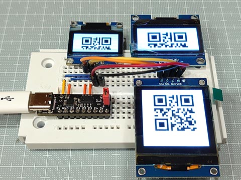
よくある安いI2C OLEDについて調べてみた。 [Arduino]
以下3つのよくあるI2CのOLEDだけど、いろいろ調べたらほぼ同じ操作でいけると判明。
・0.96インチ , 128x64 , SSD1306
・1.3インチ, 128x64, SH1106
・1.5インチ, 128x128, SH1107
★共通なところ
・5VのArduinoで、プルアップ抵抗なしで動く。
・アドレスが 0x78 (Wireライブラリでは 0x3C と1ビットずらす)
・画像メモリーの使い方、縦8ドットで1バイトが横に128個。これが縦に8ページ(あるいは16ページ)
・コマンドも大体同じっぽい
★それぞれで違うところ
*** 0.96'', 128x64 , SSD1306 ***
初期化コマンドは、0x8D, 0x14 の Enable charge pump と、0xAF の switch on OLEDの2つだけでとりあえず表示できる。
メモリがページをまたいでリニアになっているので、自然に折り返しできる。
ピンは GND VCC SCL SDA の順。
*** 1.3'', 128x64, SH1106 ***
初期化コマンドは、0xAF だけでとりあえずOK。
メモリはページをまたげない。
制御チップは132x64ドットでできているようだが、OLEDは128x64でできているので左右に2ドットずつ表示されない領域がある。
ピンは VCC GND SCL SDA の順。電源が0.96インチと逆で間違えると壊れるので注意。
*** 1.5'', 128x128, SH1107 ***
こちらも初期化コマンドは、0xAF だけでとりあえずOK。
同様にメモリはページをまたげない。
ピンは VCC GND SCL SDA の順。電源注意。
これはGME128128-01-IIC Ver 2.0での話。Ver 3は SSD1327 ?
// tinyOLEDdemo - controlling an I²C OLED (SSD1306/SH1106/SH1107) with an ATtiny202
//
// A big thank you to Stefan Wagner
// Project Files (Github):  https://github.com/wagiminator
// License: http://creativecommons.org/licenses/by-sa/3.0/

#include <avr/io.h>
#include <util/delay.h>

const uint8_t img_i[] = {   32,   32, // px
  0x00, 0x00, 0x00, 0x00, 0x00, 0x00, 0x00, 0x00, 0x00, 0x00, 0x00, 0x00, 0x00, 0x00, 0x00, 0x00,
  0x00, 0x00, 0x00, 0x82, 0xee, 0xfe, 0xfe, 0xfc, 0xf8, 0x70, 0x20, 0x00, 0x00, 0x00, 0x00, 0x00,
  0x00, 0x00, 0x00, 0x00, 0x00, 0x00, 0x00, 0x00, 0x00, 0x00, 0x00, 0x00, 0x80, 0xc0, 0xe0, 0xf0,
  0xf8, 0x7e, 0xff, 0xff, 0xef, 0xc7, 0x03, 0x01, 0x00, 0x00, 0x00, 0x00, 0x00, 0x00, 0x00, 0x00,
  0x00, 0x00, 0x00, 0x20, 0x20, 0x30, 0x10, 0x18, 0x1c, 0x0e, 0x0f, 0x07, 0x07, 0x03, 0x01, 0x01,
  0x00, 0x00, 0xff, 0xff, 0xff, 0xff, 0x00, 0x00, 0x00, 0x00, 0x00, 0x00, 0x00, 0x00, 0x00, 0x00,
  0x00, 0x00, 0x00, 0x00, 0x00, 0x00, 0x00, 0x00, 0x00, 0x00, 0x00, 0x00, 0x00, 0x00, 0x00, 0x00,
  0x00, 0x1e, 0x3f, 0x7f, 0x3f, 0x3f, 0x00, 0x00, 0x00, 0x00, 0x00, 0x00, 0x00, 0x00, 0x00, 0x00
};
const uint8_t img_qr[] = {  23,   23, // px
  0xff, 0x01, 0x7d, 0x45, 0x45, 0x45, 0x7d, 0x01, 0xff, 0x2b, 0xcb, 0x71, 0xdf, 0x01, 0xff, 0x01,
  0x7d, 0x45, 0x45, 0x45, 0x7d, 0x01, 0xff, 0xff, 0x59, 0x55, 0x7d, 0x71, 0x49, 0x67, 0x55, 0xf9,
  0x3d, 0xc2, 0x8b, 0x57, 0x91, 0x3d, 0x77, 0xc9, 0x27, 0xb9, 0x93, 0x71, 0xf7, 0xff, 0xff, 0xc0,
  0xdf, 0xd1, 0xd1, 0xd1, 0xdf, 0xc0, 0xff, 0xc1, 0xf3, 0xfa, 0xcd, 0xd5, 0xc8, 0xc5, 0xea, 0xe6,
  0xe8, 0xd8, 0xcb, 0xec, 0xff
};
// ---- I2C Master Implementation (Write only) ---------------------------------

#define I2C_FREQ  800000UL                        // I2C clock frequency in Hz
void I2C_init(void) {                             // I2C init function
  TWI0.MBAUD   = ((F_CPU / I2C_FREQ) - 10) / 2;   //   set TWI master BAUD rate (simplified BAUD calculation)
  TWI0.MCTRLA  = TWI_ENABLE_bm;                   //   enable TWI master
  TWI0.MSTATUS = TWI_BUSSTATE_IDLE_gc;            //   set bus state to idle
}
void I2C_start(uint8_t addr) {                    // I2C start transmission
  TWI0.MADDR = addr;                              //   start sending address
}
void I2C_stop(void) {                             // I2C stop transmission
  while (~TWI0.MSTATUS & TWI_WIF_bm);             //   wait for last transfer to complete
  TWI0.MCTRLB = TWI_MCMD_STOP_gc;                 //   send stop condition
}
void I2C_write(uint8_t data) {                    // I2C transmit one data byte to the slave, ignore ACK bit
  while (~TWI0.MSTATUS & TWI_WIF_bm);             //   wait for last transfer to complete
  TWI0.MDATA = data;                              //   start sending data byte
}

// ---- OLED Implementation ----------------------------------------------------

#define OLED_ADDR       0x78             // OLED write address (Wire lib.:0x3c)
#define OLED_CMD_MODE   0x00             // set command mode
#define OLED_DAT_MODE   0x40             // set data mode

const uint8_t OLED_INIT_CMD[] = {        // OLED init settings
//0xA8, 0x7F,           // set multiplex (HEIGHT-1): 0x1F(128x32), 0x3F(128x64), 0x7F(128x128)
//0x22, 0x00, 0x0f,     // set min and max page: 0x07(128x64), 0x0F(128x128)
//0x20, 0x00,           // set horizontal memory addressing mode
//0xDA, 0x12,           // set COM pins hardware configuration to alternative
  0x8D, 0x14,           // enable charge pump (for SSD1306)
  0xAF                  // switch on OLED
};

void OLED_init(void) {                    // OLED init function
  I2C_init();                             //   initialize I2C first
  I2C_start(OLED_ADDR);                   //   start transmission to OLED
  I2C_write(OLED_CMD_MODE);               //   set command mode
  for (uint8_t i=0; i<sizeof(OLED_INIT_CMD); i++) I2C_write(OLED_INIT_CMD[i]); //   send the command bytes
  I2C_stop();                             //   stop transmission
}

void OLED_cursor(uint8_t xpos, uint8_t ypos) {// OLED set the cursor
  xpos +=2;                               //  (for SH1106 (132x64)
  I2C_start(OLED_ADDR);                   //   start transmission to OLED
  I2C_write(OLED_CMD_MODE);               //   set command mode
  I2C_write(xpos & 0x0F);                 //   set low nibble of start column
  I2C_write(0x10 | (xpos >> 4));          //   set high nibble of start column
  I2C_write(0xB0 | (ypos & 0x0f));        //   set start page
  I2C_stop();                             //   stop transmission
}

void OLED_clear(uint16_t p) {             // OLED clear screen with pattern
  if( p < 256 ) p |= p << 8;
  for(uint8_t pg=0; pg<16; pg++){
    OLED_cursor(0, pg);                   //   set cursor at upper left corner
    I2C_start(OLED_ADDR);                 //   start transmission to OLED
    I2C_write(OLED_DAT_MODE);             //   set data mode
    for(uint8_t c=64; c; c--) {
      I2C_write(p & 0xff);                //   fill the screen
      I2C_write(p >> 8  );
    }
    I2C_stop();                           //   stop transmission
  }
}

void OLED_image(uint8_t xpos, uint8_t ypos, uint8_t *d) {// OLED set image
  const uint8_t w=*d++, h=*d++;
  for(uint8_t y=0; y<(h+7)/8; y++) {
    OLED_cursor(xpos, ypos + y);          //   set the cursor
    I2C_start(OLED_ADDR);                 //   start transmission to OLED
    I2C_write(OLED_DAT_MODE);             //   set data mode
    for(uint8_t x=0; x<w; x++) I2C_write( *d++ );
    I2C_stop();                           //   stop transmission
  }
}

void OLED_image2x(uint8_t xpos, uint8_t ypos, uint8_t *d) {// OLED set 2x image
  const uint8_t x2[]={ 0x0,0x3,0xc,0xf,0x30,0x33,0x3c,0x3f,0xc0,0xc3,0xcc,0xcf,0xf0,0xf3,0xfc,0xff };
  const uint8_t w=*d++, h=*d++;
  for(uint8_t y=0; y<(h+3)/4; y++) {
    OLED_cursor(xpos, ypos + y);          //   set the cursor
    I2C_start(OLED_ADDR);                 //   start transmission to OLED
    I2C_write(OLED_DAT_MODE);             //   set data mode
    for(uint8_t x=0, t; x<w; x++) {
      I2C_write( t = x2[ d[x+(y/2)*w] >> (y%2*4) & 0xf ] );
      I2C_write( t );
    }
    I2C_stop();                           //   stop transmission
  }
}

void OLED_image4x(uint8_t xpos, uint8_t ypos, uint8_t *d) {// OLED set 2x image
  const uint8_t x4[]={ 0x0,0xf,0xf0,0xff };
  const uint8_t w=*d++, h=*d++;
  for(uint8_t y=0; y<(h+1)/2; y++) {
    OLED_cursor(xpos, ypos + y);          //   set the cursor
    I2C_start(OLED_ADDR);                 //   start transmission to OLED
    I2C_write(OLED_DAT_MODE);             //   set data mode
    for(uint8_t x=0, t; x<w; x++) {
      I2C_write( t = x4[ d[x+(y/4)*w] >> (y%4*2) & 0b11 ] );
      I2C_write( t );
      I2C_write( t );
      I2C_write( t );
    }
    I2C_stop();                           //   stop transmission
  }
}

// ---- Main Function ----------------------------------------------------------

void setup() {
  _delay_ms(100);                         // add delay
  OLED_init();                            // setup I2C OLED
}

void loop() {
  OLED_clear(0x1144);                     // clear screen with pattern
  OLED_image( 48, 2, img_i );
  _delay_ms(1000);
  OLED_image2x( 32, 1, img_i );
  _delay_ms(1000);
  OLED_image4x(  0, 0, img_i );
  _delay_ms(2000);
  OLED_clear(0xff);                       // clear screen with white
  OLED_image( 52, 2, img_qr );
  _delay_ms(1000);
  OLED_image2x( 41, 1, img_qr );
  _delay_ms(1000);
  OLED_image4x( 18, 1, img_qr );
  _delay_ms(4000);
}
ATtiny202 正弦波のノイズについて調べてみた。 [Arduino]
以前、当ブログで、
202duinoで正弦波 → ノイズがのる → ATtiny412でDAC使用:放課後マイコンクラブ:SSブログ
https://hello-world.blog.ss-blog.jp/2023-06-10
というので、PWMでの疑似DACをあきらめ、1シリーズのDACでしのぎましたが、こちらの方もATtiny202のPWMでノイズが出たというのを確認しました。
ATtiny202で正弦波を作ったらノイズが入る
https://www.jh4vaj.com/archives/39505
正弦波の下り坂でノイズが入っています。
つまり、TCB0.CCMPH を減らしたときです。
いろいろ想像して、確認して、原因がわかりました。
簡単にいうと、、、
ランナー(カウンタ)が、ゴール(TCB0.CCMPH)に向かって走っているときに、ゴールが先になる場合(TCB0.CCMPHが増える場合)は問題なし。
ゴールした後に変更しても、すでに出力はLOWになっているので大きな問題はない。
だけど、ゴール(TCB0.CCMPH)が手前に来る場合(TCB0.CCMPHが減る場合)は注意。
ゴールした後(カウンタがTCB0.CCMPHを過ぎた後)にゴールを変更しても出力はLOWのままで問題なし。
あるいは、走者がゴールする前で、変更後のゴールも走者の前のときもHIGHのままで問題なし。
問題なのは、まだ走者がゴールしていないのに(カウンタがTCB0.CCMPHに達していないのに)、走者よりも後ろにゴールを設定してしまったとき(TCB0.CCMPHをカウンタよりも少ない値にしたとき)です。出力がHIGHのまま、カウンタはTOP値まで行ってしまいます。
ということで正弦波のとき限定のパッチを当ててみました。
なぜ正弦波限定なのかというと、正弦波は連続性があり前の値と大きく変わることがない(と思われる)からです。(高い音だとサンプリングの関係で値がとぶと思う。)
新しいループに入ったときに、ゴールの変更はすぐにでもできるのですが、ゴールが近い(TCB0.CCMPHの値が小さい)ときは、上記の事故がおこりうるので、ゴールした後(カウンタがTCB0.CCMPHを過ぎた後)にゴールを変更(TCB0.CCMPHを変更)すればいいということで、適当にウェイトをいれてみたところノイズのない正弦波になりました。
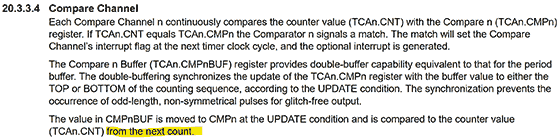
TCB0.CCMPHの更新タイミングが、カウンタが0になったときではなく、即時行われるので起こる事故(ノイズ)だったようです。
原因はわかりましたが、一般的な解決法はまだ思いつきません。
202duinoで正弦波 → ノイズがのる → ATtiny412でDAC使用:放課後マイコンクラブ:SSブログ
https://hello-world.blog.ss-blog.jp/2023-06-10
というので、PWMでの疑似DACをあきらめ、1シリーズのDACでしのぎましたが、こちらの方もATtiny202のPWMでノイズが出たというのを確認しました。
ATtiny202で正弦波を作ったらノイズが入る
https://www.jh4vaj.com/archives/39505
正弦波の下り坂でノイズが入っています。
つまり、TCB0.CCMPH を減らしたときです。
いろいろ想像して、確認して、原因がわかりました。
簡単にいうと、、、
ランナー(カウンタ)が、ゴール(TCB0.CCMPH)に向かって走っているときに、ゴールが先になる場合(TCB0.CCMPHが増える場合)は問題なし。
ゴールした後に変更しても、すでに出力はLOWになっているので大きな問題はない。
だけど、ゴール(TCB0.CCMPH)が手前に来る場合(TCB0.CCMPHが減る場合)は注意。
ゴールした後(カウンタがTCB0.CCMPHを過ぎた後)にゴールを変更しても出力はLOWのままで問題なし。
あるいは、走者がゴールする前で、変更後のゴールも走者の前のときもHIGHのままで問題なし。
問題なのは、まだ走者がゴールしていないのに(カウンタがTCB0.CCMPHに達していないのに)、走者よりも後ろにゴールを設定してしまったとき(TCB0.CCMPHをカウンタよりも少ない値にしたとき)です。出力がHIGHのまま、カウンタはTOP値まで行ってしまいます。
ということで正弦波のとき限定のパッチを当ててみました。
なぜ正弦波限定なのかというと、正弦波は連続性があり前の値と大きく変わることがない(と思われる)からです。(高い音だとサンプリングの関係で値がとぶと思う。)
新しいループに入ったときに、ゴールの変更はすぐにでもできるのですが、ゴールが近い(TCB0.CCMPHの値が小さい)ときは、上記の事故がおこりうるので、ゴールした後(カウンタがTCB0.CCMPHを過ぎた後)にゴールを変更(TCB0.CCMPHを変更)すればいいということで、適当にウェイトをいれてみたところノイズのない正弦波になりました。
TCB0.CCMPHの更新タイミングが、カウンタが0になったときではなく、即時行われるので起こる事故(ノイズ)だったようです。
原因はわかりましたが、一般的な解決法はまだ思いつきません。
// megaTinyCore ATtiny202/212/402/412 Sine Wave - PWM version
#include <util/delay_basic.h>
static const uint16_t OCTAVE9[] = { 7023, 7441, 7883, 8352, 8848, 9375, 9932, 10523,11148,11811,12513,13258 };
static const uint8_t SINE256[] = {
0, 0, 0, 0, 1, 1, 1, 2, 2, 3, 4, 5, 5, 6, 7, 9, 10, 11, 12, 14, 15, 17, 18, 20, 21, 23, 25, 27, 29, 31, 33, 35,
37, 40, 42, 44, 47, 49, 52, 54, 57, 59, 62, 65, 67, 70, 73, 76, 79, 82, 85, 88, 90, 93, 97,100,103,106,109,112,115,118,121,124,
128,131,134,137,140,143,146,149,152,155,158,162,165,167,170,173, 176,179,182,185,188,190,193,196,198,201,203,206,208,211,213,215,
218,220,222,224,226,228,230,232,234,235,237,238,240,241,243,244, 245,246,248,249,250,250,251,252,253,253,254,254,254,255,255,255,
255,255,255,255,254,254,254,253,253,252,251,250,250,249,248,246, 245,244,243,241,240,238,237,235,234,232,230,228,226,224,222,220,
218,215,213,211,208,206,203,201,198,196,193,190,188,185,182,179, 176,173,170,167,165,162,158,155,152,149,146,143,140,137,134,131,
128,124,121,118,115,112,109,106,103,100, 97, 93, 90, 88, 85, 82, 79, 76, 73, 70, 67, 65, 62, 59, 57, 54, 52, 49, 47, 44, 42, 40,
37, 35, 33, 31, 29, 27, 25, 23, 21, 20, 18, 17, 15, 14, 12, 11, 10, 9, 7, 6, 5, 5, 4, 3, 2, 2, 1, 1, 1, 0, 0, 0 };
void setup(){ // Register Settings
TCB0.CTRLA = TCB_CLKSEL_CLKDIV1_gc | TCB_ENABLE_bm; // 20MHz / 1 / 256 -> 78,125Hz
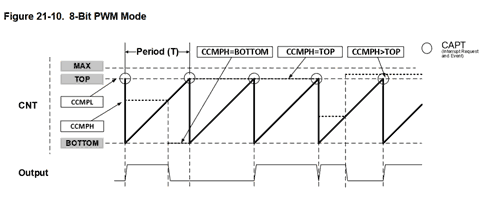
TCB0.CTRLB = TCB_CNTMODE_PWM8_gc | TCB_CCMPEN_bm; // 8-Bit PWM mode, Output Enable (WO,PA6,megaTinyCore:P0)
TCB0.CCMPL = 0xff; // top value = 255
TCB0.CCMPH = 0; // output value
}
void loop(){
sineWave( 60, 500); // C4
sineWave( 64, 500); // E4
sineWave( 67, 500); // G4
sineWave( 72, 2000); // C5
delay(1000);
}
void sineWave(uint8_t midiNum, uint16_t msDuration) {
uint16_t i, di = OCTAVE9[ midiNum % 12 ] >> (10 - midiNum / 12); // 256 times the Wave Table subscript to advance in one cycle
uint32_t cycDuration = F_CPU / 256 / 1000 * msDuration; // Convert duration to number of cycles
static uint8_t pwNew, pwNow;
do {
pwNew = SINE256[ ( (i += di) >> 8 ) ];
if( pwNew < pwNow && pwNow <120) _delay_loop_1(40); // <== Noise Reduction (wait 3x40=120cycle)
TCB0.CCMPH = pwNow = pwNew; // 8bit PWM (78,125Hz)
while( !TCB0.INTFLAGS ); // Waiting for TCB0 overflow (every 12.8usec(78,125Hz))
TCB0.INTFLAGS = TCB_CAPT_bm; // cleared by writing a '1'
} while( --cycDuration ); // Exit if note data is 0
TCB0.CCMPH = 0; // Set output to 0
}
前の10件 | -


