202duino w/ ATtiny412 で 指定波形で音楽再生<DAC版> [Arduino]
波形を指定および、DACで出力をしてみました。
ATtiny412使用です。
ダイレクトにスピーカにつなぐと音が割れました。
可変抵抗で割れないところに調整。
録音にはセラミックコンデンサーを挟んでみました。いいのか悪いのかは不明。
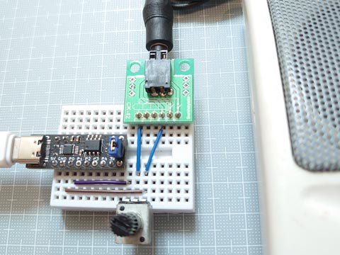
ATtiny412使用です。
ダイレクトにスピーカにつなぐと音が割れました。
可変抵抗で割れないところに調整。
録音にはセラミックコンデンサーを挟んでみました。いいのか悪いのかは不明。

// megaTinyCore ATtiny212/412 Score Replay Sketch (waveform, DAC)
#include "notes2.h"                     // Definition data of notes ( pitch (scale & octave), and note value (length))
#define MAX_TRACK   (4)                 // Maximum number of tracks
// 256 times the Wave Form subscript to advance in one cycle @ basic 12-note scale (from C9 to B9) (@20MHz, with an interrupt every 256clocks)
static const uint16_t OCTAVE9[] = { 7023, 7441, 7883, 8352, 8848, 9375, 9932, 10523,11148,11811,12513,13258 };
// waveform data
static const uint8_t  SQUARE256[] = {
    0,  0,  0,  0,  0,  0,  0,  0,  0,  0,  0,  0,  0,  0,  0,  0,   0,  0,  0,  0,  0,  0,  0,  0,  0,  0,  0,  0,  0,  0,  0,  0,
    0,  0,  0,  0,  0,  0,  0,  0,  0,  0,  0,  0,  0,  0,  0,  0,   0,  0,  0,  0,  0,  0,  0,  0,  0,  0,  0,  0,  0,  0,  0,  0,
    0,  0,  0,  0,  0,  0,  0,  0,  0,  0,  0,  0,  0,  0,  0,  0,   0,  0,  0,  0,  0,  0,  0,  0,  0,  0,  0,  0,  0,  0,  0,  0,
    0,  0,  0,  0,  0,  0,  0,  0,  0,  0,  0,  0,  0,  0,  0,  0,   0,  0,  0,  0,  0,  0,  0,  0,  0,  0,  0,  0,  0,  0,  0,  0,
  255,255,255,255,255,255,255,255,255,255,255,255,255,255,255,255, 255,255,255,255,255,255,255,255,255,255,255,255,255,255,255,255,
  255,255,255,255,255,255,255,255,255,255,255,255,255,255,255,255, 255,255,255,255,255,255,255,255,255,255,255,255,255,255,255,255,
  255,255,255,255,255,255,255,255,255,255,255,255,255,255,255,255, 255,255,255,255,255,255,255,255,255,255,255,255,255,255,255,255,
  255,255,255,255,255,255,255,255,255,255,255,255,255,255,255,255, 255,255,255,255,255,255,255,255,255,255,255,255,255,255,255,255 };
static const uint8_t  SAWTOOTH256[] = {
    0,  1,  2,  3,  4,  5,  6,  7,  8,  9, 10, 11, 12, 13, 14, 15,  16, 17, 18, 19, 20, 21, 22, 23, 24, 25, 26, 27, 28, 29, 30, 31,
   32, 33, 34, 35, 36, 37, 38, 39, 40, 41, 42, 43, 44, 45, 46, 47,  48, 49, 50, 51, 52, 53, 54, 55, 56, 57, 58, 59, 60, 61, 62, 63,
   64, 65, 66, 67, 68, 69, 70, 71, 72, 73, 74, 75, 76, 77, 78, 79,  80, 81, 82, 83, 84, 85, 86, 87, 88, 89, 90, 91, 92, 93, 94, 95,
   96, 97, 98, 99,100,101,102,103,104,105,106,107,108,109,110,111, 112,113,114,115,116,117,118,119,120,121,122,123,124,125,126,127,
  128,129,130,131,132,133,134,135,136,137,138,139,140,141,142,143, 144,145,146,147,148,149,150,151,152,153,154,155,156,157,158,159,
  160,161,162,163,164,165,166,167,168,169,170,171,172,173,174,175, 176,177,178,179,180,181,182,183,184,185,186,187,188,189,190,191,
  192,193,194,195,196,197,198,199,200,201,202,203,204,205,206,207, 208,209,210,211,212,213,214,215,216,217,218,219,220,221,222,223,
  224,225,226,227,228,229,230,231,232,233,234,235,236,237,238,239, 240,241,242,243,244,245,246,247,248,249,250,251,252,253,254,255 };
static const uint8_t  SINE256[] = {
    0,  0,  0,  0,  1,  1,  1,  2,  2,  3,  4,  5,  5,  6,  7,  9,  10, 11, 12, 14, 15, 17, 18, 20, 21, 23, 25, 27, 29, 31, 33, 35,
   37, 40, 42, 44, 47, 49, 52, 54, 57, 59, 62, 65, 67, 70, 73, 76,  79, 82, 85, 88, 90, 93, 97,100,103,106,109,112,115,118,121,124,
  128,131,134,137,140,143,146,149,152,155,158,162,165,167,170,173, 176,179,182,185,188,190,193,196,198,201,203,206,208,211,213,215,
  218,220,222,224,226,228,230,232,234,235,237,238,240,241,243,244, 245,246,248,249,250,250,251,252,253,253,254,254,254,255,255,255,
  255,255,255,255,254,254,254,253,253,252,251,250,250,249,248,246, 245,244,243,241,240,238,237,235,234,232,230,228,226,224,222,220,
  218,215,213,211,208,206,203,201,198,196,193,190,188,185,182,179, 176,173,170,167,165,162,158,155,152,149,146,143,140,137,134,131,
  128,124,121,118,115,112,109,106,103,100, 97, 93, 90, 88, 85, 82,  79, 76, 73, 70, 67, 65, 62, 59, 57, 54, 52, 49, 47, 44, 42, 40,
   37, 35, 33, 31, 29, 27, 25, 23, 21, 20, 18, 17, 15, 14, 12, 11,  10,  9,  7,  6,  5,  5,  4,  3,  2,  2,  1,  1,  1,  0,  0,  0 };
static const uint8_t PIANO256[] = {
    0,  0,  0,  1,  2,  2,  3,  4,  5,  5,  6,  7,  8,  9,  9, 10,  11, 11, 12, 13, 13, 14, 15, 17, 18, 20, 22, 25, 28, 32, 36, 40,
   45, 51, 57, 63, 70, 77, 85, 93,101,110,119,128,136,145,154,162, 170,178,185,192,198,204,210,215,219,223,227,230,233,235,237,238,
  240,241,242,242,243,244,244,245,246,246,247,248,249,250,250,251, 252,253,253,254,255,255,255,255,255,254,254,253,252,251,249,248,
  246,244,243,241,239,237,236,234,233,231,230,229,228,227,226,226, 225,225,224,224,224,223,223,222,221,221,220,218,217,215,214,212,
  209,207,205,202,200,197,194,192,189,187,185,183,181,179,178,177, 176,175,175,174,174,174,174,174,173,173,173,173,172,171,170,168,
  166,164,162,159,156,152,149,145,141,136,132,128,123,119,114,110, 106,103, 99, 96, 93, 91, 89, 87, 85, 84, 83, 82, 82, 82, 82, 81,
   81, 81, 81, 81, 80, 80, 79, 78, 77, 76, 74, 72, 70, 68, 66, 63,  61, 58, 55, 53, 50, 48, 46, 43, 41, 40, 38, 37, 35, 34, 34, 33,
   32, 32, 31, 31, 31, 30, 30, 29, 29, 28, 27, 26, 25, 24, 22, 21,  19, 18, 16, 14, 12, 11,  9,  7,  6,  4,  3,  2,  1,  1,  0,  0 };
// music data
static const uint16_t Jesus[] = {       // J.S.Bach "Jesu, Joy of Man's Desiring"
  125 , 0 ,
  b4e , g4e , a4e , b4e , d5e , c5e , c5e , e5e , d5e , d5e , g5e , F5e , g5e , d5e , b4e , g4e , a4e , b4e ,
  e4e , d5e , c5e , b4e , a4e , g4e , d4e , g4e , F4e , g4e , b4e , d5e , g5hd,                           0 ,
  d4q       , F4e , g4q       , F4e , g4q       , a4e , b4q       , a4e , b4q       , g4e , e4q       , g4e ,
  a4q       , F4e , g4q       , e4e , a3q       , c4e , b3w ,                                             0 ,
  g3qd            , e3qd            , c3qd            , b2qd            , e3qd            , d3qd            ,
  c3qd            , C3qd            , d3qd            , g2w ,                                             0 , 0 };

void setup(){                           // Register Settings
  TCB0.CTRLA = TCB_CLKSEL_CLKDIV1_gc | TCB_ENABLE_bm;   // 20MHz / 1 / 256 -> 78,125Hz
  TCB0.CTRLB = TCB_CNTMODE_PWM8_gc   | TCB_CCMPEN_bm;   // 8-Bit PWM mode, Output Enable (WO,PA6,megaTinyCore:P0)
  TCB0.CCMPL = 0xff;                                    // top value = 255
  TCB0.CCMPH = 0;                                       // output value
  VREF.CTRLA |= VREF_DAC0REFSEL_4V34_gc;                // Voltage reference at 4.34V
  VREF.CTRLB |= VREF_DAC0REFEN_bm;                      // DAC0/AC0 reference enable: enabled
  delayMicroseconds(25);                                // Wait VREF start-up time
  PORTA.PIN6CTRL &= ~PORT_ISC_gm;                       // Disable digital input buffer
  PORTA.PIN6CTRL |=  PORT_ISC_INPUT_DISABLE_gc;
  PORTA.PIN6CTRL &= ~PORT_PULLUPEN_bm;                  // Disable pull-up resistor
  DAC0.CTRLA = DAC_ENABLE_bm | DAC_OUTEN_bm;            // Enable DAC, Output Buffer
}

void loop(){
  play212wf( Jesus , SQUARE256   );     // Playback
  play212wf( Jesus , SAWTOOTH256 );     // Playback
  play212wf( Jesus , SINE256     );     // Playback
  play212wf( Jesus , PIANO256    );     // Playback
}

void play212wf( const uint16_t *d, const uint8_t *wf ){     // ATtiny212(20MHz) waveform version
  uint8_t  Tracks;                      // Number of tracks
  const uint16_t *NoteP[MAX_TRACK];     // Pointer for each track of the score
  uint16_t NoteCycle, n;                // Number of interrupt cycles required for the length of the reference note (96th note) and its counter (n)
  uint16_t note;                        // Note (pitch + note value) information read from PROGMEM
  uint8_t  len[MAX_TRACK];              // Length of note (how many 96th notes) (subtraction counter)
  uint16_t cyc[MAX_TRACK], c[MAX_TRACK];// 256 times the Wave Table subscript to advance in one cycle (cyc) and its counter (c)
  uint16_t env[MAX_TRACK];              // Sound amplitude (envelope)
  uint8_t  lap = 30;                    // Sound transitional cycles(laptime) (for Attenuation calculator)

  // *** Preparing Scores ***
  NoteCycle = F_CPU / 256 *4*60 / *d++ / MIN_NOTE;      // Number of cycles required for reference note
  for( Tracks = 0; Tracks < MAX_TRACK; ) {              // Get the number of tracks and the start position of each track from the song data
    if( *d++ != 0 ) continue;           // Skip until the break comes
    if( *d   == 0 ) break;              // If two zeros follow, end of data
    len[ Tracks ] = 1;                  // Initialize the note length subtraction counter to the remaining 1
    NoteP[ Tracks++ ] = d;              // Get location in memory, Count up the number of tracks
  }
  n = Tracks;                           // Initialize the score processing so that it can be performed immediately after the start of the do loop

  // *** Playback ***
  do {
    // * Processing Scores *
    if( --n < Tracks ) {                // Processing of score for each reference note length
      if( !--len[n] ) {
        note   = *NoteP[n]++;
        len[n] = (uint8_t) note;        // The lower 8 bits are the length of the note (how many times the length of a 96th note)
        if( note & 0xff00 ) {           // If not a rest... (Leave a lingering sound even with rests)
          cyc[n] = OCTAVE9[ (note>>8) & 0x0f ] >> (9 - (note>>12));   // 256 times the Wave Tabele subscript to advance in one cycle
            c[n] = 0;                   // Initializes a counter for the number of cycles to create one waveform cycle
          env[n] = 0xffff;              // Initially, the maximum amplitude
        }
      }
      if( !n ) n = NoteCycle;
    }
    // * Waveform Processing / Output *
    switch( Tracks ) {                  // Change output by number of tracks
      case 1:   DAC0.DATA =   wf[ (c[0]+=cyc[0])>>8 ] * (env[0]>> 8)  >>8;  // 8x8=16bit -> 8bit
                break;
      case 2:   DAC0.DATA = ( wf[ (c[0]+=cyc[0])>>8 ] * (env[0]>> 9)        // 8x7=15bit
                            + wf[ (c[1]+=cyc[1])>>8 ] * (env[1]>> 9) )>>8;  // 8x7=15bit 15/15(16bit)-> 8bit
                break;
      case 3:   DAC0.DATA = ( wf[ (c[0]+=cyc[0])>>8 ] * (env[0]>> 9)        // 8x7=15bit
                            + wf[ (c[1]+=cyc[1])>>8 ] * (env[1]>>10)        // 8x6=14bit
                            + wf[ (c[2]+=cyc[2])>>8 ] * (env[2]>>10) )>>8;  // 8x6=14bit 15/14/14(16bit)-> 8bit
                break;
      case 4:   DAC0.DATA = ( wf[ (c[0]+=cyc[0])>>8 ] * (env[0]>>10)        // 8x6=14bit
                            + wf[ (c[1]+=cyc[1])>>8 ] * (env[1]>>10)        // 8x6=14bit
                            + wf[ (c[2]+=cyc[2])>>8 ] * (env[2]>>10)        // 8x6=14bit
                            + wf[ (c[3]+=cyc[3])>>8 ] * (env[3]>>10) )>>8;  // 8x6=14bit 14/14/14/14(16bit)-> 8bit
    }
    switch( --lap ) {                   // Amplitude attenuation (Distribute processing per loop)
      case 4:   env[3] -= (env[3]>>9);    break;
      case 3:   env[2] -= (env[2]>>9);    break;
      case 2:   env[1] -= (env[1]>>9);    break;
      case 1:   env[0] -= (env[0]>>9);    break;
      case 0:   lap = 30;               // every 384usec(12.8usec*30) @20MHz (Adjustable)
    }
    while( !TCB0.INTFLAGS );            // Waiting for TCB0 overflow (every 12,8usec(78,125Hz))
    TCB0.INTFLAGS = TCB_CAPT_bm;        // cleared by writing a '1'
  } while( note );                      // Exit if note data is 0
  DAC0.DATA = 0;                        // Set output to 0
}
202duino で 減衰鋸歯状波の音楽再生 [Arduino]
実は、波形をつくって再生するスケッチを作ってみたものの、波形によってノイズが多く、ATtiny212/412のDAC使用だと目立たなくなりました。
でも、とりあえずATtiny202での再生が第一。
ノイズが目立たないのは、矩形波(作成済)と鋸歯状波形だったので、鋸歯状波形専用のスケッチをつくりました。
なんとなく8ビットゲーム音楽っぽい仕上がりです。

でも、とりあえずATtiny202での再生が第一。
ノイズが目立たないのは、矩形波(作成済)と鋸歯状波形だったので、鋸歯状波形専用のスケッチをつくりました。
なんとなく8ビットゲーム音楽っぽい仕上がりです。

// megaTinyCore ATtiny202/212/402/412 Score Replay Sketch (positive ramp sawtooth)
#include "notes2.h"                     // Definition data of notes ( pitch (scale & octave), and note value (length))
#define MAX_TRACK   (4)                 // Maximum number of tracks
// 256 times the virtual Wave Form subscript to advance in one cycle @ basic 12-note scale (from C9 to B9) (@20MHz, with an interrupt every 256clocks)
static const uint16_t OCTAVE9[] = { 7023, 7441, 7883, 8352, 8848, 9375, 9932, 10523,11148,11811,12513,13258 };
static const uint16_t Jesus[] = {       // J.S.Bach "Jesu, Joy of Man's Desiring"
  125 , 0 ,
  b4e , g4e , a4e , b4e , d5e , c5e , c5e , e5e , d5e , d5e , g5e , F5e , g5e , d5e , b4e , g4e , a4e , b4e ,
  e4e , d5e , c5e , b4e , a4e , g4e , d4e , g4e , F4e , g4e , b4e , d5e , g5hd,                           0 ,
  d4q       , F4e , g4q       , F4e , g4q       , a4e , b4q       , a4e , b4q       , g4e , e4q       , g4e ,
  a4q       , F4e , g4q       , e4e , a3q       , c4e , b3w ,                                             0 ,
  g3qd            , e3qd            , c3qd            , b2qd            , e3qd            , d3qd            ,
  c3qd            , C3qd            , d3qd            , g2w ,                                             0 , 0 };

void setup(){                           // Register Settings
  TCB0.CTRLA = TCB_CLKSEL_CLKDIV1_gc | TCB_ENABLE_bm;   // 20MHz / 1 / 256 -> 78,125Hz
  TCB0.CTRLB = TCB_CNTMODE_PWM8_gc   | TCB_CCMPEN_bm;   // 8-Bit PWM mode, Output Enable (WO,PA6,megaTinyCore:P0)
  TCB0.CCMPL = 0xff;                                    // top value = 255
  TCB0.CCMPH = 0;                                       // output value
}

void loop(){
  play202saw( Jesus );                  // Playback
}

void play202saw( const uint16_t *d ){   // ATtiny202(20MHz) sawtooth(positive ramp) version
  uint8_t  Tracks;                      // Number of tracks
  const uint16_t *NoteP[MAX_TRACK];     // Pointer for each track of the score
  uint16_t NoteCycle, n;                // Number of interrupt cycles required for the length of the reference note (96th note) and its counter (n)
  uint16_t note;                        // Note (pitch + note value) information read from PROGMEM
  uint8_t  len[MAX_TRACK];              // Length of note (how many 96th notes) (subtraction counter)
  uint16_t cyc[MAX_TRACK], c[MAX_TRACK];// 256 times the virtual Wave Table subscript to advance in one cycle (cyc) and its counter (c)
  uint16_t env[MAX_TRACK];              // Sound amplitude (envelope)
  uint8_t  lap = 30;                    // Sound transitional cycles(laptime) (for Attenuation calculator)

  // *** Preparing Scores ***
  NoteCycle = F_CPU / 256 *4*60 / *d++ / MIN_NOTE;      // Number of cycles required for reference note
  for( Tracks = 0; Tracks < MAX_TRACK; ) {              // Get the number of tracks and the start position of each track from the song data
    if( *d++ != 0 ) continue;           // Skip until the break comes
    if( *d   == 0 ) break;              // If two zeros follow, end of data
    len[ Tracks ] = 1;                  // Initialize the note length subtraction counter to the remaining 1
    NoteP[ Tracks++ ] = d;              // Get location in memory, Count up the number of tracks
  }
  n = Tracks;                           // Initialize the score processing so that it can be performed immediately after the start of the do loop

  // *** Playback ***
  do {
    // * Processing Scores *
    if( --n < Tracks ) {                // Processing of score for each reference note length
      if( !--len[n] ) {
        note   = *NoteP[n]++;
        len[n] = (uint8_t) note;        // The lower 8 bits are the length of the note (how many times the length of a 96th note)
        if( note & 0xff00 ) {           // If not a rest... (Leave a lingering sound even with rests)
          cyc[n] = OCTAVE9[ (note>>8) & 0x0f ] >> (9 - (note>>12));     // 256 times the Wave Table subscript to advance in one cycle
            c[n] = 0;                   // Initializes a counter for the number of cycles to create one waveform cycle
          env[n] = 0xffff;              // Initially, the maximum amplitude
        }
      }
      if( !n ) n = NoteCycle;
    }
    // * Waveform Processing / Output *
    switch( Tracks ) {                  // Change output by number of tracks
      case 1:   TCB0.CCMPH =   ((c[0]+=cyc[0])>>8) * (env[0]>> 8)  >>8; // 8x8=16bit -> 8bit
                break;
      case 2:   TCB0.CCMPH = ( ((c[0]+=cyc[0])>>8) * (env[0]>> 9)       // 8x7=15bit
                             + ((c[1]+=cyc[1])>>8) * (env[1]>> 9) )>>8; // 8x7=15bit 15/15(16bit)-> 8bit
                break;
      case 3:   TCB0.CCMPH = ( ((c[0]+=cyc[0])>>8) * (env[0]>> 9)       // 8x7=15bit
                             + ((c[1]+=cyc[1])>>8) * (env[1]>>10)       // 8x6=14bit
                             + ((c[2]+=cyc[2])>>8) * (env[2]>>10) )>>8; // 8x6=14bit 15/14/14(16bit)-> 8bit
                break;
      case 4:   TCB0.CCMPH = ( ((c[0]+=cyc[0])>>8) * (env[0]>>10)       // 8x6=14bit
                             + ((c[1]+=cyc[1])>>8) * (env[1]>>10)       // 8x6=14bit
                             + ((c[2]+=cyc[2])>>8) * (env[2]>>10)       // 8x6=14bit
                             + ((c[3]+=cyc[3])>>8) * (env[3]>>10) )>>8; // 8x6=14bit 14/14/14/14(16bit)-> 8bit
    }
    switch( --lap ) {                   // Amplitude attenuation (Distribute processing per loop)
      case 4:   env[3] -= (env[3]>>9);    break;
      case 3:   env[2] -= (env[2]>>9);    break;
      case 2:   env[1] -= (env[1]>>9);    break;
      case 1:   env[0] -= (env[0]>>9);    break;
      case 0:   lap = 30;               // every 384usec(12.8usec*30) @20MHz (Adjustable)
    }
    while( !TCB0.INTFLAGS );            // Waiting for TCB0 overflow (every 12.8usec(78,125Hz))
    TCB0.INTFLAGS = TCB_CAPT_bm;        // cleared by writing a '1'
  } while( note );                      // Exit if note data is 0
  TCB0.CCMPH = 0;                       // Set output to 0
}
202duino で 減衰矩形波の音楽再生 [Arduino]
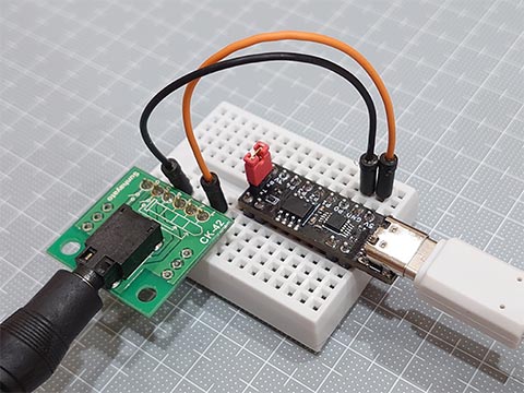
減衰矩形波での音楽再生スケッチをATtiny202用に調整してみた。
正弦波の実験ではノイズが出たのに矩形波ではノイズが目立たなくなった。
(直接スピーカーに接続です。アンプとかは壊れる可能性があるのでダメ。)
よくわからない。
以下、スケッチ。
20MHz用に調整してあります。
"note2.h" は以下参照
Digisparkで音楽演奏【楽譜編】
https://hello-world.blog.ss-blog.jp/2022-07-04
正弦波の実験ではノイズが出たのに矩形波ではノイズが目立たなくなった。
(直接スピーカーに接続です。アンプとかは壊れる可能性があるのでダメ。)
よくわからない。

以下、スケッチ。
20MHz用に調整してあります。
//  megaTinyCore ATtiny202/212/402/412 Score Replay Sketch
#include "notes2.h"                     // Definition data of notes ( pitch (scale & octave), and note value (length))
#define MAX_TRACK   (4)                 // Maximum number of tracks
// Number of cycles that are the wavelength of the basic 12-note scale (from C0 to B0) (@20MHz, with an interrupt every 256clocks)
static const uint16_t CYC_SCALE[] = { 4778, 4510, 4257, 4018, 3792, 3579, 3378, 3189, 3010, 2841, 2681, 2531 };
// music data
static const uint16_t Jesus[] = {       // J.S.Bach "Jesu, Joy of Man's Desiring"
  125 , 0 ,
  b4e , g4e , a4e , b4e , d5e , c5e , c5e , e5e , d5e , d5e , g5e , F5e , g5e , d5e , b4e , g4e , a4e , b4e ,
  e4e , d5e , c5e , b4e , a4e , g4e , d4e , g4e , F4e , g4e , b4e , d5e , g5hd,                           0 ,
  d4q       , F4e , g4q       , F4e , g4q       , a4e , b4q       , a4e , b4q       , g4e , e4q       , g4e ,
  a4q       , F4e , g4q       , e4e , a3q       , c4e , b3w ,                                             0 ,
  g3qd            , e3qd            , c3qd            , b2qd            , e3qd            , d3qd            ,
  c3qd            , C3qd            , d3qd            , g2w ,                                             0 , 0 };

void setup(){                           // Register Settings
  TCB0.CTRLA = TCB_CLKSEL_CLKDIV1_gc | TCB_ENABLE_bm;   // 20MHz / 1 / 256 -> 78,125Hz
  TCB0.CTRLB = TCB_CNTMODE_PWM8_gc   | TCB_CCMPEN_bm;   // 8-Bit PWM mode, Output Enable (WO,PA6,megaTinyCore:P0)
  TCB0.CCMPL = 0xff;                                    // top value = 255
  TCB0.CCMPH = 0;                                       // output value
}

void loop(){
  play202( Jesus );                     // Playback
  delay(1000);
}

void play202(const uint16_t *d){        // ATtiny202(20MHz) version
  uint8_t  Tracks;                      // Number of tracks
  const uint16_t *NoteP[MAX_TRACK];     // Pointer for each track of the score
  uint16_t NoteCycle, n;                // Number of interrupt cycles required for the length of the reference note (96th note) and its counter (n)
  uint16_t note;                        // Note (pitch + note value) information read from PROGMEM
  uint8_t  len[MAX_TRACK];              // Length of note (how many 96th notes) (subtraction counter)
  uint16_t cyc[MAX_TRACK], c[MAX_TRACK];// Number of interrupt cycles (cyc) required for one sound wavelength cycle and its counter (c)
  uint16_t env[MAX_TRACK];              // Sound amplitude (envelope)
  uint16_t wav[MAX_TRACK];              // Output value
  uint8_t  lap = 30;                    // Sound transitional cycles(laptime) (for Attenuation calculator)

  // *** Preparing Scores ***
  NoteCycle = F_CPU / 256 *4*60 / *d++ / MIN_NOTE;      // Number of cycles required for reference note
  for( Tracks = 0; Tracks < MAX_TRACK; ) {              // Get the number of tracks and the start position of each track from the song data
    if( *d++ != 0 ) continue;           // Skip until the break comes
    if( *d   == 0 ) break;              // If two zeros follow, end of data
    len[ Tracks ] = 1;                  // Initialize the note length subtraction counter to the remaining 1
    NoteP[ Tracks++ ] = d;              // Get location in memory, Count up the number of tracks
  }
  n = Tracks;                           // Initialize the score processing so that it can be performed immediately after the start of the do loop

  // *** Playback ***
  do {
    // * Processing Scores *
    if( --n < Tracks ) {                // Processing of score for each reference note length
      if( !--len[n] ) {
        note   = *NoteP[n]++;
        len[n] = (uint8_t) note;        // The lower 8 bits are the length of the note (how many times the length of a 96th note)
        cyc[n] = (note>>8) ? CYC_SCALE[ (note>>8) & 0xf ] >> (note>>12) : 0;    // Upper 4 bits are octave, next 4 bits are pitch class (0-11), 0 for rests
          c[n] = 0;                     // Initialize the counter for the number of cycles to create one square wave cycle
        env[n] = 0xffff;                // Initially, the maximum amplitude
      }
      if( !n ) n = NoteCycle;
    }
    // * Waveform Processing / Output *
    switch( Tracks ) {                  // Create output data, Square wave with duty ratio of 1:1
      case 4:   wav[3] = ( ( c[3] = (++c[3]==cyc[3]) ? 0 : c[3] ) < (cyc[3]>>1) ) ? env[3] : 0;   [[fallthrough]];
      case 3:   wav[2] = ( ( c[2] = (++c[2]==cyc[2]) ? 0 : c[2] ) < (cyc[2]>>1) ) ? env[2] : 0;   [[fallthrough]];
      case 2:   wav[1] = ( ( c[1] = (++c[1]==cyc[1]) ? 0 : c[1] ) < (cyc[1]>>1) ) ? env[1] : 0;   [[fallthrough]];
      case 1:   wav[0] = ( ( c[0] = (++c[0]==cyc[0]) ? 0 : c[0] ) < (cyc[0]>>1) ) ? env[0] : 0;
    }
    switch( Tracks ) {                  // WO(ATtiny202:PA1) Change output by number of tracks
      case 1:   TCB0.CCMPH =   wav[0] >>8;                                   break;
      case 2:   TCB0.CCMPH = ((wav[0]>>1) + (wav[1]>>1)) >>8;                break;
      case 3:   TCB0.CCMPH = ((wav[0]>>1) + (wav[1]>>2) + (wav[2]>>2)) >>8;  break;
      case 4:   TCB0.CCMPH = ((wav[0]>>2) + (wav[1]>>2) + (wav[2]>>2) + (wav[3]>>2)) >>8;
    }
    switch( --lap ) {                   // Amplitude attenuation (Distribute processing per loop)
      case 4:   env[3] -= (env[3]>>9);    break;
      case 3:   env[2] -= (env[2]>>9);    break;
      case 2:   env[1] -= (env[1]>>9);    break;
      case 1:   env[0] -= (env[0]>>9);    break;
      case 0:   lap = 30;               // every 384usec(12.8usec*30) @20MHz (Adjustable)
    }
    while( !TCB0.INTFLAGS );            // Waiting for TCB0 overflow (every 12.8usec(78,125Hz))
    TCB0.INTFLAGS = TCB_CAPT_bm;        // cleared by writing a '1'
  } while( note );                      // Exit if note data is 0
  TCB0.CCMPH = 0;                       // Set output to 0
}
"note2.h" は以下参照
Digisparkで音楽演奏【楽譜編】
https://hello-world.blog.ss-blog.jp/2022-07-04
RL78/G15 FPB の書き込み速度改善 [Arduino]
以前、RL78/G15 FPB ではスケッチの書き込みに30秒ほどかかって、ブレッドボードのRL78/G15にCH340なら5秒くらいで終わったというのがあったのですが、どうやらFDTIのシリアル書き込み界隈ではよくある話のようで、
デバイスマネージャー → ポート(COM と LPT) → USB Serial Port(COM_)のプロパティ → ポートの設定 → 詳細設定... → BMオプション まで行き、
待ち時間 (msec): 16 を 1 に変更するということでした。
一定のデータ量に達するか、この時間が経過したときにデータを送るっぽい。
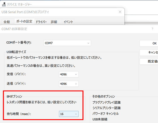
設定を変えたら、内臓のFT232RQでも、sparkfunのFT232RLでも早くなりました。
ただ、
っていうエラーメッセージが時おり出るようになってしまった。
デバイスマネージャー → ポート(COM と LPT) → USB Serial Port(COM_)のプロパティ → ポートの設定 → 詳細設定... → BMオプション まで行き、
待ち時間 (msec): 16 を 1 に変更するということでした。
一定のデータ量に達するか、この時間が経過したときにデータを送るっぽい。

設定を変えたら、内臓のFT232RQでも、sparkfunのFT232RLでも早くなりました。
ただ、
シリアルポート「
」が選択されていますが、そのポートは存在しないか、ボードが接続されていません。
っていうエラーメッセージが時おり出るようになってしまった。
202duinoで正弦波 → ノイズがのる → ATtiny412でDAC使用 [Arduino]
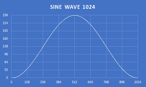
ATtiny202で正弦波をつくってみたんだけど、おそらく慣れないPWMの操作に問題があると思われ、ノイズがのってしまいました。
そこで、tinyAVR 1-Series の ATtiny412 を使用した「202duino w/ ATtiny412」でDACを使ってみることにしました。
せっかくなので正弦波のサンプリングも4倍にしたりしてみました。
//  megaTinyCore ATtiny202/212/402/412 Sine Wave
static const uint16_t OCTAVE9[] = { 7023, 7441, 7883, 8352, 8848, 9375, 9932, 10523,11148,11811,12513,13258 };
static const uint8_t  SINE256[] = {
    0,  0,  0,  0,  1,  1,  1,  2,  2,  3,  4,  5,  5,  6,  7,  9,  10, 11, 12, 14, 15, 17, 18, 20, 21, 23, 25, 27, 29, 31, 33, 35,
   37, 40, 42, 44, 47, 49, 52, 54, 57, 59, 62, 65, 67, 70, 73, 76,  79, 82, 85, 88, 90, 93, 97,100,103,106,109,112,115,118,121,124,
  128,131,134,137,140,143,146,149,152,155,158,162,165,167,170,173, 176,179,182,185,188,190,193,196,198,201,203,206,208,211,213,215,
  218,220,222,224,226,228,230,232,234,235,237,238,240,241,243,244, 245,246,248,249,250,250,251,252,253,253,254,254,254,255,255,255,
  255,255,255,255,254,254,254,253,253,252,251,250,250,249,248,246, 245,244,243,241,240,238,237,235,234,232,230,228,226,224,222,220,
  218,215,213,211,208,206,203,201,198,196,193,190,188,185,182,179, 176,173,170,167,165,162,158,155,152,149,146,143,140,137,134,131,
  128,124,121,118,115,112,109,106,103,100, 97, 93, 90, 88, 85, 82,  79, 76, 73, 70, 67, 65, 62, 59, 57, 54, 52, 49, 47, 44, 42, 40,
   37, 35, 33, 31, 29, 27, 25, 23, 21, 20, 18, 17, 15, 14, 12, 11,  10,  9,  7,  6,  5,  5,  4,  3,  2,  2,  1,  1,  1,  0,  0,  0 };

void setup(){                   // Register Settings
  TCB0.CTRLA = TCB_CLKSEL_CLKDIV1_gc | TCB_ENABLE_bm;   // 20MHz / 1 / 256 -> 78,125Hz
  TCB0.CTRLB = TCB_CNTMODE_PWM8_gc   | TCB_CCMPEN_bm;   // 8-Bit PWM mode, Output Enable (WO,PA6,megaTinyCore:P0)
  TCB0.CCMPL = 0xff;                                    // top value = 255
  TCB0.CCMPH = 0;                                       // output value
}

void loop(){
  sineWave( 60,  500);          // C4
  sineWave( 64,  500);          // E4
  sineWave( 67,  500);          // G4
  sineWave( 72, 2000);          // C5
  delay(1000);
}

void sineWave(uint8_t midiNum, uint16_t msDuration) {
  uint16_t i, di = OCTAVE9[ midiNum % 12 ] >> (10 - midiNum / 12);  // 256 times the Wave Table subscript to advance in one cycle
  uint32_t cycDuration = F_CPU / 256 / 1000 * msDuration;           // Convert duration to number of cycles
  do {
    TCB0.CCMPH = SINE256[ ( (i += di) >> 8 ) ];         // 8bit PWM (78,125Hz)
    while( !TCB0.INTFLAGS );                            // Waiting for TCB0 overflow (every 12.8usec(78,125Hz))
    TCB0.INTFLAGS = TCB_CAPT_bm;                        // cleared by writing a '1'
  } while( --cycDuration );                             // Exit if note data is 0
  TCB0.CCMPH = 0;                                       // Set output to 0
}
そこで、tinyAVR 1-Series の ATtiny412 を使用した「202duino w/ ATtiny412」でDACを使ってみることにしました。
せっかくなので正弦波のサンプリングも4倍にしたりしてみました。

202duino で Real-Time Counter (RTC) の練習 [Arduino]
ATtiny202でのRTCを調べてみた。
Getting Started with RTC
https://ww1.microchip.com/downloads/en/Appnotes/TB3213-Getting-Started-with-RTC-DS90003213B.pdf
ここにサンプルがあったので、megaTinyCore の ATtiny202 用に、さらにシンプルにしてみた。
RTC Overflow Interrupt Code Example
(0.5秒毎にLEDを点滅させる)
RTC Periodic Interrupt Code Example
(1秒毎にLEDを点滅させる)
スリープ関連のサンプルもあったけど、202duinoは、常にtype-Cから電源をとること、CH340E常時ONということもあり、まあいっか、、ということで。
Getting Started with RTC
https://ww1.microchip.com/downloads/en/Appnotes/TB3213-Getting-Started-with-RTC-DS90003213B.pdf
ここにサンプルがあったので、megaTinyCore の ATtiny202 用に、さらにシンプルにしてみた。
RTC Overflow Interrupt Code Example
(0.5秒毎にLEDを点滅させる)
// RTC Overflow Interrupt Code Example

void setup() {
  PORTA.DIRSET = PIN6_bm;
  PORTA.OUTSET = PIN6_bm;
  while (RTC.STATUS > 0);               // Wait for all register to be synchronized
  RTC.PER = 511;                        // Set period
  RTC.CLKSEL   = RTC_CLKSEL_INT32K_gc;  // 32.768kHz Internal Crystal Oscillator
  RTC.DBGCTRL |= RTC_DBGRUN_bm;         // Run in debug: enabled
  RTC.CTRLA    = RTC_PRESCALER_DIV32_gc // 32
               | RTC_RTCEN_bm           // Enable: enabled
               | RTC_RUNSTDBY_bm;       // Run In Standby: enabled
  RTC.INTCTRL |= RTC_OVF_bm;            // Enable Overflow Interrupt
}

void loop() {
}

ISR(RTC_CNT_vect)
{
  RTC.INTFLAGS = RTC_OVF_bm;            // Clear flag by writing '1':  LED0_toggle();
  PORTA.OUTTGL = PIN6_bm;               // LED toggle
}
RTC Periodic Interrupt Code Example
(1秒毎にLEDを点滅させる)
// RTC Periodic Interrupt Code Example

void setup() {
  PORTA.DIRSET = PIN6_bm;
  PORTA.OUTSET = PIN6_bm;
  while (RTC.STATUS > 0);               // Wait for all register to be synchronized
  RTC.CLKSEL   = RTC_CLKSEL_INT32K_gc;  // 32.768kHz Internal Crystal Oscillator
  RTC.DBGCTRL |= RTC_DBGRUN_bm;         // Run in debug: enabled
  RTC.PITINTCTRL = RTC_PI_bm;           // Periodic Interrupt: enabled
  RTC.PITCTRLA = RTC_PERIOD_CYC32768_gc // RTC Clock Cycles 32768
               | RTC_PITEN_bm;          // Enable: enabled
  pinMode( LED_BUILTIN, OUTPUT);
}

void loop() {
}

ISR(RTC_PIT_vect)
{
  RTC.PITINTFLAGS = RTC_PI_bm;          // Clear flag by writing '1':
  PORTA.OUTTGL    = PIN6_bm;            // LED toggle
}

スリープ関連のサンプルもあったけど、202duinoは、常にtype-Cから電源をとること、CH340E常時ONということもあり、まあいっか、、ということで。
202duino でPWMを使ってリモコン送信 [Arduino]
ATtiny202 の PWM の練習にリモコン信号の作成をしてみました。
2年ほど前にテレビをSONY製に替えたので、それで試してみます。

通常のリモコンでは電源はトグル操作になっていますが、テレビの状態にかかわらずON/OFFを操作する隠しコードがあるということでネットから探してきました。
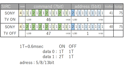
PWMは40kHzです。8bitのPWMだと、CPUが20MHzの場合、20MHz / 256(8bitの最大パルス周期) = 78.125 KHz となり、これより周波数を上げることはできても下げることはできません。そこで2分周して、20MHz / 2分周 / 40kHz = 250 で、TOP値を255 (8bit)以内に収めました。
TCA(16-bit Timer/Counter Type A) は megaTinyCore の時間関連で使われているようなので、TCB(16-Bit Timer/Counter Type B) (tone()やServoで使用?)を使用しました。
ATtiny202の場合、TCB0からのPWM出力はWO (Waveform Output)であり、SOIC(8-Pin)の2番、Pin nameでPA6、megaTinyCore での 0番となります。
修正:usTrailer = 70 x 0.6msec = 420usecでなくて42000usecだった。
2年ほど前にテレビをSONY製に替えたので、それで試してみます。

通常のリモコンでは電源はトグル操作になっていますが、テレビの状態にかかわらずON/OFFを操作する隠しコードがあるということでネットから探してきました。

PWMは40kHzです。8bitのPWMだと、CPUが20MHzの場合、20MHz / 256(8bitの最大パルス周期) = 78.125 KHz となり、これより周波数を上げることはできても下げることはできません。そこで2分周して、20MHz / 2分周 / 40kHz = 250 で、TOP値を255 (8bit)以内に収めました。
TCA(16-bit Timer/Counter Type A) は megaTinyCore の時間関連で使われているようなので、TCB(16-Bit Timer/Counter Type B) (tone()やServoで使用?)を使用しました。
ATtiny202の場合、TCB0からのPWM出力はWO (Waveform Output)であり、SOIC(8-Pin)の2番、Pin nameでPA6、megaTinyCore での 0番となります。
// Infrared remote control with 40kHz PWM (ATtiny202, SIRC version)
inline void   TCB0_PWM_ON()   { TCB0.CTRLB |=  TCB_CCMPEN_bm; }     // CCMPEN enable
inline void   TCB0_PWM_OFF()  { TCB0.CTRLB &= ~TCB_CCMPEN_bm; }     // CCMPEN disable

void setup() {                                          // Create 40kHz
  TCB0.CTRLA = TCB_CLKSEL_CLKDIV2_gc | TCB_ENABLE_bm;   // 20MHz / 2 / 250 -> 40kHz
  TCB0.CTRLB = TCB_CNTMODE_PWM8_gc;                     // 8-Bit PWM mode
  TCB0.CCMPL = F_CPU / 2 / 40000 - 1;                   // top value (249@20MHz, 199@16MHz for 40kHz)
  TCB0.CCMPH = F_CPU / 2 / 40000 / 3;                   // duty cycle = 1/3
  PORTA.DIRSET = PIN6_bm;                               // WO (PA6, megaTinyCore:P0)
}

void loop() {
  sendIrSIRC202( 46 | 1UL << 7 );                       // SONY TV ON  (cmd:46(7bit), adrs:1(5bit))
  sendIrSIRC202( 46 | 1UL << 7 );                       //   repeat 3 times
  sendIrSIRC202( 46 | 1UL << 7 );
  delay( 5000 );
  sendIrSIRC202( 47 | 1UL << 7 );                       // SONY TV OFF (cmd:47(7bit), adrs:1(5bit))
  sendIrSIRC202( 47 | 1UL << 7 );                       //   repeat 3 times
  sendIrSIRC202( 47 | 1UL << 7 );
  delay( 5000 );
}

void sendIrSIRC202( uint32_t d ) {                      //   T = 0.60msec
  uint8_t  b = (d & 0xF8000) ? 20 :
               (d & 0x07000) ? 15 : 12;                 // number of bits
  uint16_t usON, usTrailer = 42000;                     // 70T = interval(75T) - leader(5T)
  TCB0_PWM_ON();  delayMicroseconds( 2400 );            // leader ON  (4T)
  TCB0_PWM_OFF(); delayMicroseconds(  600 );            // leader OFF (1T)
  for(uint8_t i = 0; i < b; i++) {                      // data(command + address)
    usON = ((d>>i)&1) ? 1200 : 600;                     // data(0:1T / 1:2T)
    TCB0_PWM_ON();  delayMicroseconds( usON );          // data ON
    TCB0_PWM_OFF(); delayMicroseconds(  600 );          // data OFF (1T)
    usTrailer -= (usON + 600);                          // trailer
  }
  delayMicroseconds( usTrailer );
}
修正:usTrailer = 70 x 0.6msec = 420usecでなくて42000usecだった。


