202duino で Charlieplexing [Arduino]
事前に環境設定でボードマネージャの追加などしておきます。
megaTinyCore_Installation.md at master · SpenceKonde_megaTinyCore · GitHub
https://github.com/SpenceKonde/megaTinyCore/blob/master/Installation.md
The boards manager URL is:
作成した 202duino 、、ちゃんと5ピン全ピン使用できるか、LEDのCharlieplexingで確認してみました。
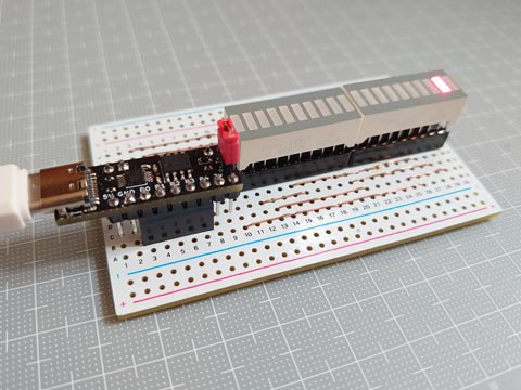
10連LEDを2個使って、20個のLEDを操作。
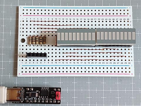
表は一見きれい。
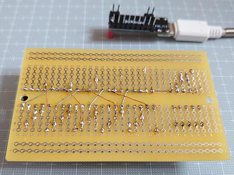
裏はきたない。ぼくの嫌いなエナメル線を使用。
<202duino専用スケッチ>
AVR 0シリーズの直接ポート操作もしてみた。
megaTinyCore_Ref_DirectPortManipulation.md at master · SpenceKonde_megaTinyCore · GitHub
https://github.com/SpenceKonde/megaTinyCore/blob/master/megaavr/extras/Ref_DirectPortManipulation.md
レジスタはいじらない代わりに、操作ピン数、操作ピン番号、LED数を指定するだけでいい汎用スケッチも作ってみた。4ピン 10LEDのやつでも確認済。
<汎用スケッチ>
megaTinyCore_Installation.md at master · SpenceKonde_megaTinyCore · GitHub
https://github.com/SpenceKonde/megaTinyCore/blob/master/Installation.md
The boards manager URL is:
http://drazzy.com/package_drazzy.com_index.json
作成した 202duino 、、ちゃんと5ピン全ピン使用できるか、LEDのCharlieplexingで確認してみました。
10連LEDを2個使って、20個のLEDを操作。
表は一見きれい。
裏はきたない。ぼくの嫌いなエナメル線を使用。
<202duino専用スケッチ>
// Drive 20 LEDs with 5 pins
const uint8_t PoK[20] = {  0,0,0,0,1,1,1,1,2,2,  2,2,3,3,3,3,4,4,4,4  };    // Pin of Cathode(K) (-)
//                       +---------------------+---------------------+
//                       | | | | | | | | | | | | | | | | | | | | | | |
//                       | _ _ _ _ _ _ _ _ _ _ | _ _ _ _ _ _ _ _ _ _ | Cathode(K)
//                       | ^ ^ ^ ^ ^ ^ ^ ^ ^ ^ | ^ ^ ^ ^ ^ ^ ^ ^ ^ ^ | Anode(A)
//                       | | | | | | | | | | | | | | | | | | | | | | |
//                       +---------------------+---------------------+
const uint8_t PoA[20] = {  1,2,3,4,0,2,3,4,0,1,  3,4,0,1,2,4,0,1,2,3  };    // Pin of Anode(A)   (+)
const uint8_t P2PA[5] = { PIN6_bm, PIN7_bm, PIN1_bm, PIN2_bm, PIN3_bm };    // Pin to PORTA

void setup() {
}

void loop() {
static uint8_t pos = 0, dir = true;         // Position and Direction(0:-, 1:+) of light
  lightUpPA( dir ? pos++ : pos-- );
  delay(50);
  if(pos == 19 || pos == 0) dir = 1 ^ dir;  // change direction when the light reach the edge
}

void lightUpPA(uint8_t n){                  // PORTA form
  for(uint8_t i=0; i<5; i++) {
    if     ( PoA[n]==i ) PORTA.DIRSET = PORTA.OUTSET = P2PA[i];     // set anode HIGH
    else if( PoK[n]==i ) PORTA.DIRSET = PORTA.OUTCLR = P2PA[i];     // set cathode LOW
    else                 PORTA.DIRCLR = P2PA[i];                    // set to Hi-Z (input)
  }
}
AVR 0シリーズの直接ポート操作もしてみた。
megaTinyCore_Ref_DirectPortManipulation.md at master · SpenceKonde_megaTinyCore · GitHub
https://github.com/SpenceKonde/megaTinyCore/blob/master/megaavr/extras/Ref_DirectPortManipulation.md
レジスタはいじらない代わりに、操作ピン数、操作ピン番号、LED数を指定するだけでいい汎用スケッチも作ってみた。4ピン 10LEDのやつでも確認済。
<汎用スケッチ>
// Drive N*(N-1) LEDs with N pins
#define NoL       20                                // number of LEDs
#define NoP       5                                 // number of pins
const uint8_t     P2INO[NoP]= { 0, 1, 2, 3, 4 };    // LED Pin to Arduino pin
#define PoK(n)  ((n)/((NoP)-1))                     // LED Pin of Cathode(K) (-)
#define PoA(n)  ((1+(n)*((NoP)+1)/(NoP))%(NoP))     // LED Pin of Anode(A)   (+)

void setup() {
}

void loop() {
  static uint8_t pos = 0, dir = true;       // Position and Direction(0:-, 1:+) of light
  lightUp( dir ? pos++ : pos-- );
  delay(100);
  if(pos == (min(NoL, (NoP)*((NoP)-1))-1) || pos == 0) dir = 1 ^ dir;   // change direction when the light reach the edge
}

void lightUp(uint8_t n){
  for(uint8_t i=0; i<NoP; i++) {
    if( PoA(n)==i || PoK(n)==i ) {          // If the pin is connected to the anode or cathode of the LED,
      pinMode( P2INO[i], OUTPUT );          //   set to output pin
      digitalWrite( P2INO[i], PoA(n)==i );  //   set cathode LOW, set anode HIGH
    } else {
      pinMode( P2INO[i], INPUT  );          // Set to Hi-Z
    }
  }
}


