202duino の SPI で NeoPixel [Arduino]
NTSCビデオ信号のドット幅がなかなかそろわず、SPIに手を出そうと、、。
SPIでデータを送る練習としてNeoPixelで実験。
以前に作ったのと同様にNeoPixel棒を光らせられました。
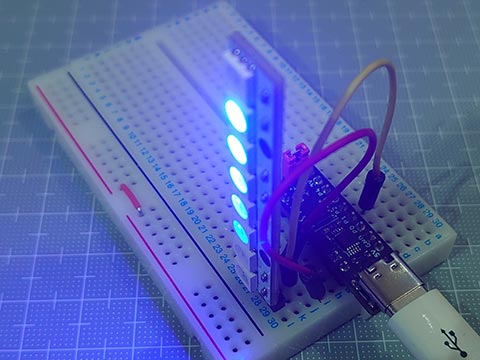
202duino で NeoPixel [Arduino]
https://hello-world.blog.ss-blog.jp/2023-07-15
スケッチサイズは582バイトと軽量に。
WS2812Bのデータシートには、
Data transfar Time
0 : High 220- 380ns / Low 580-1000ns
1 : High 580-1000ns / Low 580-1000ns
ってあるけと、どうやら Highの時間の長短で0/1を決めているみたいで、Lowの時間は厳密に守らなくてもいいみたい。
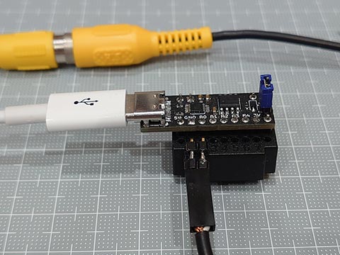
問題点は、ATtiny202は実質の有効ピンが5ピンにも関わらず、SPIを使うと、MOSIの他、MISO、SCK も使ってしまうので、他に使える残りのピンが2本になってしまい、あまり実用的ではないかも。
というわけで、NTSCビデオ計画はちょっと保留。
SPIでデータを送る練習としてNeoPixelで実験。
以前に作ったのと同様にNeoPixel棒を光らせられました。
202duino で NeoPixel [Arduino]
https://hello-world.blog.ss-blog.jp/2023-07-15
スケッチサイズは582バイトと軽量に。
// ATtiny202 SPI NeoPixel test (20MHz)

#define T0        (0b11100000)  // T0H : 300ns @ 20MHz CLK2X DIV4
#define T1        (0b11111100)  // T1H : 600ns @ 20MHz CLK2X DIV4
#define NUMPIXELS (12)

uint8_t pixels[NUMPIXELS * 3];  // GRBGRBGRB...

void setup() {
  PORTA.DIRSET = _BV(1);        // PA1(MOSI) OUTPUT (megaTinyCore:D2)
  SPI0.CTRLA   = SPI_MASTER_bm | SPI_CLK2X_bm | SPI_PRESC_DIV4_gc | SPI_ENABLE_bm;
  SPI0.CTRLB   = SPI_BUFEN_bm | SPI_BUFWR_bm | SPI_SSD_bm | SPI_MODE_1_gc;
}

void loop() {
  for (uint8_t i = 0; i < NUMPIXELS; i++) {
    for (uint8_t c = 0; c < 6; c++) {
        pixels[ ((NUMPIXELS + i - c) * 3 + 2) % (NUMPIXELS * 3) ] = 31 >> c;
    }
    neoPixelShow();
    delay(100);
  }
}

void neoPixelShow() {
  for(uint8_t i = 0; i < NUMPIXELS * 3; i++) {
    for(uint8_t bm = 0b10000000; bm; bm >>= 1) {
      SPI0.DATA = (pixels[i] & bm) ? T1 : T0;
      while( !(SPI0.INTFLAGS & SPI_DREIF_bm) );
    }
  }
}
WS2812Bのデータシートには、
Data transfar Time
0 : High 220- 380ns / Low 580-1000ns
1 : High 580-1000ns / Low 580-1000ns
ってあるけと、どうやら Highの時間の長短で0/1を決めているみたいで、Lowの時間は厳密に守らなくてもいいみたい。
問題点は、ATtiny202は実質の有効ピンが5ピンにも関わらず、SPIを使うと、MOSIの他、MISO、SCK も使ってしまうので、他に使える残りのピンが2本になってしまい、あまり実用的ではないかも。
というわけで、NTSCビデオ計画はちょっと保留。
ATtiny412でNTSCビデオ信号 [Arduino]
NTSCでのビデオ出力。
いろいろ調べてみたけど、結構たいへん。
1.情報収集
小さなカラーLCDなども安価になってきていて、いまどきマイコンでNTSCでのビデオ出力する人が少なくなっている。記事をさぐると10年くらい前のものが多く、リンク切れも多数。
カラー、ノンインターレスの説明は見つかるものの、基本のモノクロとノンインターレスの情報が少なめ。PICでの情報が多めな感じ。
2.ソフトウェア
全部あるいは部分的にアセンブラを使わないといけなかったり、SPIを出力につかったり。
とくにカラーは超高難度のよう。
別ICと組み合わせが必要なものも。
3.ハードウェア
簡単なものだと同期信号と画像信号と2本の抵抗を介して出力。
外部クロックを使用しないと画像が揺らぐらしい。
そこで、C言語だけで、tinyAVR 1シリーズのDAC機能を使って、コネクタ以外の外付けパーツなしでビデオ出力できるかやってみました。
とりあえずできたけど、ウェイトなしで横16ドットしか表示できていない。
もうちょっとなんとかなりそうな気もする。

[2023/11/02]
その後、ちょっと改善
・割り算をなくした
・16ビットでなくてもいい変数は8ビットに
・データを1ドットあたり1byte → 1bitとした
・for文を使わず、配列の添え字を変数にせず、すべて展開
(横1ドットにつきプログラム1行)
などで、横128ドットまでは行きついた。
同期をなんとかせねば。

[2023/11/03]
ジッター(揺らぎ)の原因がプログラムの問題なのか、クリスタルの有無の問題なのか、SYNCとVIDEOと2本の抵抗を使ってATmega328のArduinoに移植してみた。
1ドット毎の幅が違うから右端がそろわないけど、くっきりになった。

やっぱりクリスタルがないとダメってことか。
[2023/11/03]
いろいろ修正しながらATtint202でやってみた。
ジッター(揺らぎ)はあるものの、くっきりはした。エッジがぼやけるのはDACのせいだったらしい。

もうちょっと形になったらブログに上げたい。
いろいろ調べてみたけど、結構たいへん。
1.情報収集
小さなカラーLCDなども安価になってきていて、いまどきマイコンでNTSCでのビデオ出力する人が少なくなっている。記事をさぐると10年くらい前のものが多く、リンク切れも多数。
カラー、ノンインターレスの説明は見つかるものの、基本のモノクロとノンインターレスの情報が少なめ。PICでの情報が多めな感じ。
2.ソフトウェア
全部あるいは部分的にアセンブラを使わないといけなかったり、SPIを出力につかったり。
とくにカラーは超高難度のよう。
別ICと組み合わせが必要なものも。
3.ハードウェア
簡単なものだと同期信号と画像信号と2本の抵抗を介して出力。
外部クロックを使用しないと画像が揺らぐらしい。
そこで、C言語だけで、tinyAVR 1シリーズのDAC機能を使って、コネクタ以外の外付けパーツなしでビデオ出力できるかやってみました。
とりあえずできたけど、ウェイトなしで横16ドットしか表示できていない。
もうちょっとなんとかなりそうな気もする。
// ATtiny412 NTSC test (20MHz)
#define   IRE_p100  (59)        // = 255 * 1.0V/4.34V * (40+100)/140
#define   IRE_p50   (38)        // = 255 * 1.0V/4.34V * (40+ 50)/140
#define   IRE_0     (17)        // = 255 * 1.0V/4.34V *  40     /140
#define   IRE_m40   (0)

uint8_t const img_i[] = {
  0,0,0,0,0,0,0,0,0,1,1,0,0,0,0,0,
  0,0,0,0,0,0,0,0,0,0,1,1,0,0,0,0,
  0,0,0,0,0,0,0,0,0,0,1,1,1,0,0,0,
  0,0,0,0,0,0,0,0,0,1,1,1,0,0,0,0,
  0,0,0,0,0,0,0,0,1,1,1,0,0,0,0,0,
  0,0,0,0,0,0,0,0,1,1,0,0,0,0,0,0,
  0,0,0,0,0,0,0,1,1,1,0,0,0,0,0,0,
  0,0,0,0,0,0,1,1,0,1,1,0,0,0,0,0,
  0,0,0,0,1,1,1,0,0,1,1,0,0,0,0,0,
  0,0,0,1,1,0,0,0,0,1,1,0,0,0,0,0,
  0,1,1,0,0,0,0,0,0,1,1,0,0,0,0,0,
  0,0,0,0,0,0,0,0,0,1,1,0,0,0,0,0,
  0,0,0,0,0,0,0,0,0,1,1,0,0,0,0,0,
  0,0,0,0,0,0,0,0,1,1,1,0,0,0,0,0,
  0,0,0,0,0,0,0,0,1,1,1,0,0,0,0,0,
  0,0,0,0,0,0,0,0,0,1,1,0,0,0,0,0,
  0,0,0,0,0,0,0,0,0,0,0,0,0,0,0,0
};

void setup(){                           // Register Settings
  // VIDEO OUTPUT
    VREF.CTRLA |= VREF_DAC0REFSEL_4V34_gc;              // Voltage reference at 4.34V
    VREF.CTRLB |= VREF_DAC0REFEN_bm;                    // DAC0/AC0 reference enable: enabled
    delayMicroseconds(25);                              // Wait VREF start-up time
    PORTA.PIN6CTRL &= ~PORT_ISC_gm;                     // Disable digital input buffer
    PORTA.PIN6CTRL |=  PORT_ISC_INPUT_DISABLE_gc;
    PORTA.PIN6CTRL &= ~PORT_PULLUPEN_bm;                // Disable pull-up resistor
    DAC0.CTRLA = DAC_ENABLE_bm | DAC_OUTEN_bm;          // Enable DAC, Output Buffer
  // H-SYNC
    TCB0.CTRLA  = TCB_CLKSEL_CLKDIV1_gc | TCB_ENABLE_bm;// 20MHz / 1 / 1270 -> 15,750Hz
    TCB0.CTRLB  = TCB_CNTMODE_INT_gc;                   // periodic Interrupt mode
    TCB0_CCMP   = 1269;                                 // top value
    TCB0.INTCTRL= TCB_CAPT_bm;                          // Capture Interrupt Enable
}

void loop() {
}

ISR(TCB0_INT_vect) {
  static uint16_t scan, x, y, offset;
  DAC0.DATA = IRE_0;                                    // start from -3.2usec
  scan++;
  while(TCB0_CNT <  94);                                // front porch (20MHz*(3.2+1.5    )usec=94)
  DAC0.DATA = IRE_m40;
  if(scan > 3  && scan < 7)   goto END;
  while(TCB0_CNT < 188);                                // back porch  (20MHz*(3.2+1.5+4.7)usec=188)
  DAC0.DATA = IRE_0;
  if(scan < 48 || scan > 239) goto END;                 // 192 lines
  y = (scan - 48) / 12;                                 // y = 0..15
  offset= y<<4;
  while(TCB0_CNT < 282);                                // H-blanking  (20MHz*(3.2+10.9   )usec=282)
  MAIN:
  for(x=0; x<16; x++) {
    DAC0.DATA = (img_i[x + offset]) ? IRE_p100 : IRE_0;
  }
  DAC0.DATA = IRE_0;
  END:
  if(scan == 262) scan = 0;
  TCB0.INTFLAGS= TCB_CAPT_bm;                           // Clear Capture Interrupt Flag
}
[2023/11/02]
その後、ちょっと改善
・割り算をなくした
・16ビットでなくてもいい変数は8ビットに
・データを1ドットあたり1byte → 1bitとした
・for文を使わず、配列の添え字を変数にせず、すべて展開
(横1ドットにつきプログラム1行)
などで、横128ドットまでは行きついた。
同期をなんとかせねば。
[2023/11/03]
ジッター(揺らぎ)の原因がプログラムの問題なのか、クリスタルの有無の問題なのか、SYNCとVIDEOと2本の抵抗を使ってATmega328のArduinoに移植してみた。
1ドット毎の幅が違うから右端がそろわないけど、くっきりになった。
やっぱりクリスタルがないとダメってことか。
[2023/11/03]
いろいろ修正しながらATtint202でやってみた。
ジッター(揺らぎ)はあるものの、くっきりはした。エッジがぼやけるのはDACのせいだったらしい。
もうちょっと形になったらブログに上げたい。
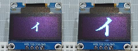
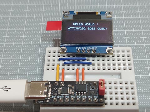
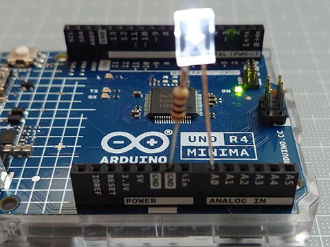
I2C OLED (SSD1306)に画像を出す。Wire版 [Arduino]
Wireライブラリー + delay() を使って一般的なArduinoでだいたい動くようにしました。
・ATtiny 412 (megaTinyCore)
・UNO R1 (ATmega328)
・UNO R4 MINIMA (RA4M1)
・RL78/G15 Fast Prototyping Board
で動くことを確認しました。
ATyiny202には 2269バイトとフラッシュメモリ 2kByteをオーバーしてしまい不可でした。
こんな感じで、、
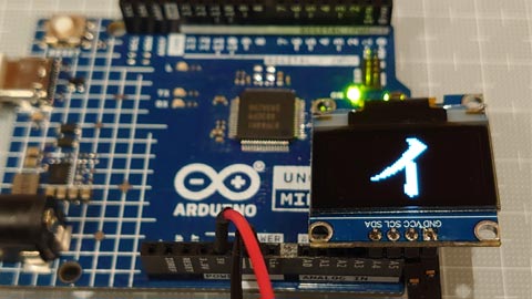
ブレッドボードなしでつないでみた。
・ATtiny 412 (megaTinyCore)
・UNO R1 (ATmega328)
・UNO R4 MINIMA (RA4M1)
・RL78/G15 Fast Prototyping Board
で動くことを確認しました。
ATyiny202には 2269バイトとフラッシュメモリ 2kByteをオーバーしてしまい不可でした。
こんな感じで、、
ブレッドボードなしでつないでみた。
// tinyOLEDdemo - controlling an I²C OLED (SSD1306)
#include <Wire.h>
uint8_t const img_i[] = { 32, 32, // px
0x00, 0x00, 0x00, 0x00, 0x00, 0x00, 0x00, 0x00, 0x00, 0x00, 0x00, 0x00, 0x00, 0x00, 0x00, 0x00,
0x00, 0x00, 0x00, 0x82, 0xee, 0xfe, 0xfe, 0xfc, 0xf8, 0x70, 0x20, 0x00, 0x00, 0x00, 0x00, 0x00,
0x00, 0x00, 0x00, 0x00, 0x00, 0x00, 0x00, 0x00, 0x00, 0x00, 0x00, 0x00, 0x80, 0xc0, 0xe0, 0xf0,
0xf8, 0x7e, 0xff, 0xff, 0xef, 0xc7, 0x03, 0x01, 0x00, 0x00, 0x00, 0x00, 0x00, 0x00, 0x00, 0x00,
0x00, 0x00, 0x00, 0x20, 0x20, 0x30, 0x10, 0x18, 0x1c, 0x0e, 0x0f, 0x07, 0x07, 0x03, 0x01, 0x01,
0x00, 0x00, 0xff, 0xff, 0xff, 0xff, 0x00, 0x00, 0x00, 0x00, 0x00, 0x00, 0x00, 0x00, 0x00, 0x00,
0x00, 0x00, 0x00, 0x00, 0x00, 0x00, 0x00, 0x00, 0x00, 0x00, 0x00, 0x00, 0x00, 0x00, 0x00, 0x00,
0x00, 0x1e, 0x3f, 0x7f, 0x3f, 0x3f, 0x00, 0x00, 0x00, 0x00, 0x00, 0x00, 0x00, 0x00, 0x00, 0x00
};
uint8_t const img_qr[] = { 23, 23, // px
0xff, 0x01, 0x7d, 0x45, 0x45, 0x45, 0x7d, 0x01, 0xff, 0x2b, 0xcb, 0x71, 0xdf, 0x01, 0xff, 0x01,
0x7d, 0x45, 0x45, 0x45, 0x7d, 0x01, 0xff, 0xff, 0x59, 0x55, 0x7d, 0x71, 0x49, 0x67, 0x55, 0xf9,
0x3d, 0xc2, 0x8b, 0x57, 0x91, 0x3d, 0x77, 0xc9, 0x27, 0xb9, 0x93, 0x71, 0xf7, 0xff, 0xff, 0xc0,
0xdf, 0xd1, 0xd1, 0xd1, 0xdf, 0xc0, 0xff, 0xc1, 0xf3, 0xfa, 0xcd, 0xd5, 0xc8, 0xc5, 0xea, 0xe6,
0xe8, 0xd8, 0xcb, 0xec, 0xff
};
// ---- OLED Implementation ----------------------------------------------------
#define OLED_ADDR 0x3c // OLED write address (Wire lib.:0x3c)
#define OLED_CMD_MODE 0x00 // set command mode
#define OLED_DAT_MODE 0x40 // set data mode
const uint8_t OLED_INIT_CMD[] = { // OLED init settings
0xA8, 0x3F, // set multiplex (HEIGHT-1): 0x1F for 128x32, 0x3F for 128x64
0x22, 0x00, 0x07, // set min and max page
0x20, 0x00, // set horizontal memory addressing mode
0xDA, 0x12, // set COM pins hardware configuration to alternative
0x8D, 0x14, // enable charge pump
0xAF // switch on OLED
};
void OLED_init(void) { // OLED init function
Wire.begin(); // initialize I2C first
Wire.beginTransmission(OLED_ADDR); // start transmission to OLED
Wire.write(OLED_CMD_MODE); // set command mode
for (uint8_t i=0; i<sizeof(OLED_INIT_CMD); i++) Wire.write(OLED_INIT_CMD[i]); // send the command bytes
Wire.endTransmission(); // stop transmission
}
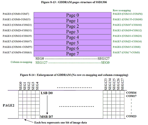
void OLED_cursor(uint8_t xpos, uint8_t ypos) {// OLED set the cursor
Wire.beginTransmission(OLED_ADDR); // start transmission to OLED
Wire.write(OLED_CMD_MODE); // set command mode
Wire.write(xpos & 0x0F); // set low nibble of start column
Wire.write(0x10 | (xpos >> 4)); // set high nibble of start column
Wire.write(0xB0 | (ypos & 0x07)); // set start page
Wire.endTransmission(); // stop transmission
}
void OLED_clear(uint8_t p) { // OLED clear screen with pattern
OLED_cursor(0, 0); // set cursor at upper left corner
for(uint8_t j=1024/16; j; j--) {
Wire.beginTransmission(OLED_ADDR); // start transmission to OLED
Wire.write(OLED_DAT_MODE); // set data mode
for(uint8_t i=16; i; i--) Wire.write(p);// clear the screen with p
Wire.endTransmission(); // stop transmission
}
}
void OLED_image(uint8_t xpos, uint8_t ypos, const uint8_t *d) {// OLED set image
const uint8_t w=*d++, h=*d++;
for(uint8_t y=0, i=0; y<(h+7)/8; y++) {
OLED_cursor(xpos, ypos + y); // set the cursor
for(uint8_t x=0; x<w; x++) {
if( !i ) {
Wire.beginTransmission(OLED_ADDR);// start transmission to OLED
Wire.write(OLED_DAT_MODE); // set data mode
}
Wire.write( *d++ );
if( ++i==31 || w-x==1 ) {
Wire.endTransmission(); // stop transmission
i=0;
}
}
}
}
void OLED_image2x(uint8_t xpos, uint8_t ypos, const uint8_t *d) {// OLED set 2x image
const uint8_t x2[]={ 0x0,0x3,0xc,0xf,0x30,0x33,0x3c,0x3f,0xc0,0xc3,0xcc,0xcf,0xf0,0xf3,0xfc,0xff };
const uint8_t w=*d++, h=*d++;
for(uint8_t y=0, i=0; y<(h+3)/4; y++) {
OLED_cursor(xpos, ypos + y); // set the cursor
for(uint8_t x=0, t; x<w; x++) {
if( !i ) {
Wire.beginTransmission(OLED_ADDR);// start transmission to OLED
Wire.write(OLED_DAT_MODE); // set data mode
}
Wire.write( t = x2[ d[x+(y/2)*w] >> (y%2*4) & 0xf ] );
Wire.write( t );
if( (i+=2)>29 || w-x==1 ) {
Wire.endTransmission(); // stop transmission
i=0;
}
}
}
}
// ---- Main Function ----------------------------------------------------------
void setup() {
delay(100); // add delay
OLED_init(); // setup I2C OLED
}
void loop() {
OLED_clear(0x00); // clear screen with black
OLED_image( 48, 2, img_i );
delay(1000);
OLED_image2x( 32, 0, img_i );
delay(2000);
OLED_clear(0xff); // clear screen with white
OLED_image( 52, 2, img_qr );
delay(1000);
OLED_image2x( 40, 1, img_qr );
delay(4000);
}
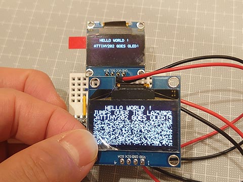
I2C OLED (SSD1306)に画像を出す。ATtiny202版 [Arduino]
ATtiny202でI2C OLEDに画像を出すスケッチをつくってみた。
GitHub - wagiminator_ATtiny13-TinyOLEDdemo I²C OLED on an ATtiny10_13_202
https://github.com/wagiminator/ATtiny13-TinyOLEDdemo
これを参考に、、といっても、データを流すだけで画像が出るようにデータ配列に変換してあるので大したことはしてません。
そこで、2倍に拡大した画像も出せるようにしてみました。
ややジャギーが気になるけど、、
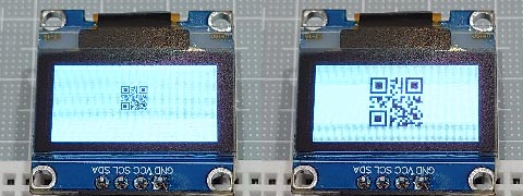
QRコードなら問題なし。
スケッチも1247バイトと軽量。
GitHub - wagiminator_ATtiny13-TinyOLEDdemo I²C OLED on an ATtiny10_13_202
https://github.com/wagiminator/ATtiny13-TinyOLEDdemo
これを参考に、、といっても、データを流すだけで画像が出るようにデータ配列に変換してあるので大したことはしてません。
そこで、2倍に拡大した画像も出せるようにしてみました。
ややジャギーが気になるけど、、
QRコードなら問題なし。
スケッチも1247バイトと軽量。
// tinyOLEDdemo - controlling an I²C OLED (SSD1306) with an ATtiny202
//
// A big thank you to Stefan Wagner
// Project Files (Github):  https://github.com/wagiminator
// License: http://creativecommons.org/licenses/by-sa/3.0/

#include <avr/io.h>
#include <util/delay.h>

const uint8_t img_i[] = {   32,   32, // px
  0x00, 0x00, 0x00, 0x00, 0x00, 0x00, 0x00, 0x00, 0x00, 0x00, 0x00, 0x00, 0x00, 0x00, 0x00, 0x00,
  0x00, 0x00, 0x00, 0x82, 0xee, 0xfe, 0xfe, 0xfc, 0xf8, 0x70, 0x20, 0x00, 0x00, 0x00, 0x00, 0x00,
  0x00, 0x00, 0x00, 0x00, 0x00, 0x00, 0x00, 0x00, 0x00, 0x00, 0x00, 0x00, 0x80, 0xc0, 0xe0, 0xf0,
  0xf8, 0x7e, 0xff, 0xff, 0xef, 0xc7, 0x03, 0x01, 0x00, 0x00, 0x00, 0x00, 0x00, 0x00, 0x00, 0x00,
  0x00, 0x00, 0x00, 0x20, 0x20, 0x30, 0x10, 0x18, 0x1c, 0x0e, 0x0f, 0x07, 0x07, 0x03, 0x01, 0x01,
  0x00, 0x00, 0xff, 0xff, 0xff, 0xff, 0x00, 0x00, 0x00, 0x00, 0x00, 0x00, 0x00, 0x00, 0x00, 0x00,
  0x00, 0x00, 0x00, 0x00, 0x00, 0x00, 0x00, 0x00, 0x00, 0x00, 0x00, 0x00, 0x00, 0x00, 0x00, 0x00,
  0x00, 0x1e, 0x3f, 0x7f, 0x3f, 0x3f, 0x00, 0x00, 0x00, 0x00, 0x00, 0x00, 0x00, 0x00, 0x00, 0x00
};
const uint8_t img_qr[] = {  23,   23, // px
  0xff, 0x01, 0x7d, 0x45, 0x45, 0x45, 0x7d, 0x01, 0xff, 0x2b, 0xcb, 0x71, 0xdf, 0x01, 0xff, 0x01,
  0x7d, 0x45, 0x45, 0x45, 0x7d, 0x01, 0xff, 0xff, 0x59, 0x55, 0x7d, 0x71, 0x49, 0x67, 0x55, 0xf9,
  0x3d, 0xc2, 0x8b, 0x57, 0x91, 0x3d, 0x77, 0xc9, 0x27, 0xb9, 0x93, 0x71, 0xf7, 0xff, 0xff, 0xc0,
  0xdf, 0xd1, 0xd1, 0xd1, 0xdf, 0xc0, 0xff, 0xc1, 0xf3, 0xfa, 0xcd, 0xd5, 0xc8, 0xc5, 0xea, 0xe6,
  0xe8, 0xd8, 0xcb, 0xec, 0xff
};
// ---- I2C Master Implementation (Write only) ---------------------------------

#define I2C_FREQ  800000UL                        // I2C clock frequency in Hz
void I2C_init(void) {                             // I2C init function
  TWI0.MBAUD   = ((F_CPU / I2C_FREQ) - 10) / 2;   //   set TWI master BAUD rate (simplified BAUD calculation)
  TWI0.MCTRLA  = TWI_ENABLE_bm;                   //   enable TWI master
  TWI0.MSTATUS = TWI_BUSSTATE_IDLE_gc;            //   set bus state to idle
}
void I2C_start(uint8_t addr) {                    // I2C start transmission
  TWI0.MADDR = addr;                              //   start sending address
}
void I2C_stop(void) {                             // I2C stop transmission
  while (~TWI0.MSTATUS & TWI_WIF_bm);             //   wait for last transfer to complete
  TWI0.MCTRLB = TWI_MCMD_STOP_gc;                 //   send stop condition
}
void I2C_write(uint8_t data) {                    // I2C transmit one data byte to the slave, ignore ACK bit
  while (~TWI0.MSTATUS & TWI_WIF_bm);             //   wait for last transfer to complete
  TWI0.MDATA = data;                              //   start sending data byte
}

// ---- OLED Implementation ----------------------------------------------------

#define OLED_ADDR       0x78             // OLED write address (Wire lib.:0x3c)
#define OLED_CMD_MODE   0x00             // set command mode
#define OLED_DAT_MODE   0x40             // set data mode

const uint8_t OLED_INIT_CMD[] = {        // OLED init settings
  0xA8, 0x3F,           // set multiplex (HEIGHT-1): 0x1F for 128x32, 0x3F for 128x64
  0x22, 0x00, 0x07,     // set min and max page
  0x20, 0x00,           // set horizontal memory addressing mode
  0xDA, 0x12,           // set COM pins hardware configuration to alternative
  0x8D, 0x14,           // enable charge pump
  0xAF                  // switch on OLED
};

void OLED_init(void) {                    // OLED init function
  I2C_init();                             //   initialize I2C first
  I2C_start(OLED_ADDR);                   //   start transmission to OLED
  I2C_write(OLED_CMD_MODE);               //   set command mode
  for (uint8_t i=0; i<sizeof(OLED_INIT_CMD); i++) I2C_write(OLED_INIT_CMD[i]); //   send the command bytes
  I2C_stop();                             //   stop transmission
}

void OLED_cursor(uint8_t xpos, uint8_t ypos) {// OLED set the cursor
  I2C_start(OLED_ADDR);                   //   start transmission to OLED
  I2C_write(OLED_CMD_MODE);               //   set command mode
  I2C_write(xpos & 0x0F);                 //   set low nibble of start column
  I2C_write(0x10 | (xpos >> 4));          //   set high nibble of start column
  I2C_write(0xB0 | (ypos & 0x07));        //   set start page
  I2C_stop();                             //   stop transmission
}

void OLED_clear(uint8_t p) {              // OLED clear screen with pattern
  OLED_cursor(0, 0);                      //   set cursor at upper left corner
  I2C_start(OLED_ADDR);                   //   start transmission to OLED
  I2C_write(OLED_DAT_MODE);               //   set data mode
  for(uint16_t i=1024; i; i--) I2C_write(p);  // clear the screen
  I2C_stop();                             //   stop transmission
}

void OLED_image(uint8_t xpos, uint8_t ypos, uint8_t *d) {// OLED set image
  const uint8_t w=*d++, h=*d++;
  for(uint8_t y=0; y<(h+7)/8; y++) {
    OLED_cursor(xpos, ypos + y);          //   set the cursor
    I2C_start(OLED_ADDR);                 //   start transmission to OLED
    I2C_write(OLED_DAT_MODE);             //   set data mode
    for(uint8_t x=0; x<w; x++) I2C_write( *d++ );
    I2C_stop();                           //   stop transmission
  }
}

void OLED_image2x(uint8_t xpos, uint8_t ypos, uint8_t *d) {// OLED set 2x image
  const uint8_t x2[]={ 0x0,0x3,0xc,0xf,0x30,0x33,0x3c,0x3f,0xc0,0xc3,0xcc,0xcf,0xf0,0xf3,0xfc,0xff };
  const uint8_t w=*d++, h=*d++;
  for(uint8_t y=0; y<(h+3)/4; y++) {
    OLED_cursor(xpos, ypos + y);          //   set the cursor
    I2C_start(OLED_ADDR);                 //   start transmission to OLED
    I2C_write(OLED_DAT_MODE);             //   set data mode
    for(uint8_t x=0, t; x<w; x++) {
      I2C_write( t = x2[ d[x+(y/2)*w] >> (y%2*4) & 0xf ] );
      I2C_write( t );
    }
    I2C_stop();                           //   stop transmission
  }
}

// ---- Main Function ----------------------------------------------------------

void setup() {
  _delay_ms(100);                         // add delay
  OLED_init();                            // setup I2C OLED
}

void loop() {
  OLED_clear(0x00);                       // clear screen with black
  OLED_image( 48, 2, img_i );
  _delay_ms(1000);
  OLED_image2x( 32, 0, img_i );
  _delay_ms(2000);
  OLED_clear(0xff);                       // clear screen with white
  OLED_image( 52, 2, img_qr );
  _delay_ms(1000);
  OLED_image2x( 41, 1, img_qr );
  _delay_ms(4000);
}
0.96インチI2C OLED (SSD1306)用に画像をデータ配列に。 [JavaScript]
Aliexpressで安いI2C OLEDディスプレイとなると、0.96インチの制御チップがSSD1306のもの。
とりあえず画像を出してみたいけど、BMPファイルデータをArduinoで動的に変換する必要はないので、SSD1306に合わせて画像をデータ配列にしたほうがいい。
自作のスクリプトを作った後、すでに画像変換できるサイトがあることが判明。
image2cpp
http://javl.github.io/image2cpp/
ただ、いろいろできる分、設定もたくさんある。
ぼくの作ったのは、サンプルプログラムの寄せ集めだけど、ドラッグ&ドロップでSSD1306専用のデータが瞬時にできるというのが売り。
高さが8の倍数でないときの余白部分を白にするか黒にするかの選択のみ。
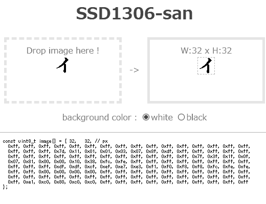
HTMLソース
とりあえず画像を出してみたいけど、BMPファイルデータをArduinoで動的に変換する必要はないので、SSD1306に合わせて画像をデータ配列にしたほうがいい。
自作のスクリプトを作った後、すでに画像変換できるサイトがあることが判明。
image2cpp
http://javl.github.io/image2cpp/
ただ、いろいろできる分、設定もたくさんある。
ぼくの作ったのは、サンプルプログラムの寄せ集めだけど、ドラッグ&ドロップでSSD1306専用のデータが瞬時にできるというのが売り。
高さが8の倍数でないときの余白部分を白にするか黒にするかの選択のみ。
HTMLソース
<html>
<head><meta charset="utf-8"><title>SSD1306-san</title></head>
<body style="color:#999; text-align:center;">
<h1 style="color:#666;">SSD1306-san</h1>
<div style="display:flex; justify-content:center; align-items:center;">
<div id="target" style="width:200px; height:100px; border:5px dashed #eee; padding:10px;">
Drop image here !<br>
<img id="preview" style="max-width:200px; max-height:80px;" onLoad="ssd1306img()"><br></div>
<div style="width: 50px; "> -> </div>
<div style="width:200px; height:100px; border:5px solid #eee; padding:10px;">
<span id="info" ></span><br>
<canvas id="cvs" style="max-width:128px; max-height:64px; border:1px dashed #ccc; display:none"></canvas></div></div>
<div>
<p>background color :
<input id="bgw" type="radio" name="bg" checked><label for="bgw">white</label>
<input id="bgb" type="radio" name="bg" ><label for="bgb">black</label>
<p><textarea id="ary" cols=100 rows=20 style="font-size:80%; padding:1em; border:1px solid #ccc;" onClick="this.select()"></textarea></div>
<script>
function $(x) { return document.getElementById(x); }
const ctx = $('cvs').getContext('2d');
$('target').addEventListener('dragover', function (e) {
e.preventDefault();
e.stopPropagation();
e.dataTransfer.dropEffect = 'copy'; } );
$('target').addEventListener('drop', function (e) {
e.stopPropagation();
e.preventDefault();
const reader = new FileReader();
reader.onload = function (e) { preview.src = e.target.result; }
reader.readAsDataURL(e.dataTransfer.files[0]); } );
function ssd1306img() {
const w = $('cvs').width = $('preview').naturalWidth;
const h = $('cvs').height = $('preview').naturalHeight;
const H = h - (h - 1) % 8 + 7;
$('info').innerHTML = "W:" + w + " x H:" + h;
$('cvs').style.display = "none";
$('ary').textContent = " Image size is too large! ";
if( w > 128 || h > 64 ) return;
$('cvs').style.display = "inline";
$('ary').textContent = "const uint8_t image[] = { " + w + ", " + h + ", // px\n ";
ctx.fillStyle = $('bgw').checked ? '#fff' : '#000';
ctx.fillRect(0, 0, w, H);
ctx.drawImage($('preview'), 0, 0);
const img = ctx.getImageData(0, 0, w, h);
let i, d, x, y, b;
for (i = 0; i < img.data.length; i += 4) {
const gray = img.data[i] * 0.299 + img.data[i+1] * 0.587 + img.data[i+2] * 0.114;
img.data[i] = img.data[i+1] = img.data[i+2] = gray > 127 ? 255 : 0;
}
ctx.putImageData(img, 0, 0);
for (i = y = 0; y < H; y += 8) {
for (x = 0; x < w; x++) {
for (b = d = 0; b < 8; b++) d += img.data[(x+(y+b)*w)*4] ? (1<<b) : 0;
$('ary').textContent += (d < 16 ? "0x0" : "0x") + d.toString(16) + ((++i % 16) ? ", ": ",\n ");
}
}
$('ary').textContent = $('ary').textContent.slice( 0, $('ary').textContent.lastIndexOf(',') ) + "\n};";
}
</script>
</body>
</html>
202duino で I2C OLEDディスプレイ [Arduino]
ちょっと前にAliexpressで買ったままになっていた I2C OLED ディスプレイを出してみた。
SSD1306という制御チップを使ったもの。
プルアップ抵抗なしでもなんとかなった。
ATtiny202で制御できるかどうか調べてみると、、ありました。
GitHub - wagiminator_ATtiny13-TinyOLEDdemo I²C OLED on an ATtiny10_13_202
https://github.com/wagiminator/ATtiny13-TinyOLEDdemo
ここで使われているのは、128 x 32 ドット用のスケッチなので、128 x 64 ドット用にちょっと変更するとふつうに使えました。
変更箇所の1つめは、
// OLED init settings
const uint8_t OLED_INIT_CMD[] = {
  0xA8, 0x3F,       // set multiplex (HEIGHT-1): 0x1F for 128x32, 0x3F for 128x64                   HEIGHT-1   : 0x1F --> 0x3F
  0x22, 0x00, 0x07, // set min and max page                                                         max page   : 0x03 --> 0x07
  0x20, 0x01,       // set vertical memory addressing mode
  0xDA, 0x12,       // set COM pins hardware configuration to sequential                            0x02:Sequential --> 0x12:Alternative
  0x8D, 0x14,       // enable charge pump
  0xAF,             // switch on OLED
  0x00, 0x10, 0xB0, // set cursor at home position
  0xA1, 0xC8        // flip the screen
};
2つめは、// Setup のところで、OLED_init();の前にちょっとdelayを入れること。
3つめは、OLED_clear(void) で、512 → 1024 に変更すること。
です。
delayもArduino標準のを使わずAVRのdelayを使ったりして、スケッチも1kBほどにおさまっています。
試しにこのスケッチを「Wire(I2C)ライブラリ」,「delay()」を使って書き換えてみました。
注意点というか、嵌った点。
・アドレスを 0x78 → 0x3C と1ビットずらした表記で指定する。
・write()というのは書きだすのではなくて溜めておくだけで、endTransmission()で書き出す。
・溜めて置けるのは32バイトまで。
ということで、単純な置換だけではなく、関数の修正も必要でした。
で、それをするとどうなるかというと、、
・そこそこ遅くなっているような気がする
・スケッチが大きくなる(ATtiny202の2kBに収まらなくなり、ATtiny412を使用した。)
・他のArduinoでも使える(UNO R4でも表示できた。)
1.3インチのものも出てきたので使ってみたら、表示できるにはできるけどおかしい。
似て非なる制御チップを使っているらしい。(SH1106?)
0.96インチのと1.3インチのもので電源ピンの順番が逆になっていて、一つ壊してしまった。
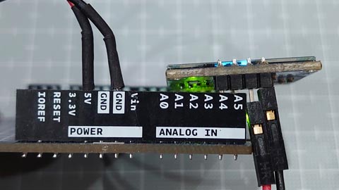
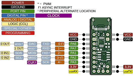
202duinoのピン配列をよくあるやつっぽく作ってみた。

QUHSSHIK 0.96インチOLED I2C IIC 通信 128*64 OLEDモジュールデジタルディスプレイ回路基板自発光スペアパーツ, 白
- 出版社/メーカー: QUHSSHIK
- メディア:
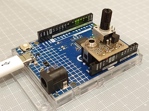
UNO R4 とスピーカをつなぐシールドを作ってみた。 [Arduino]
DACで音声再生ができたものの、圧電サウンダの小さな音ではさみしい。
スピーカーでそこそこの音量での再生にチャレンジ。
使用したのは、10kΩの可変抵抗とNPNトランジスタと3.5mmジャック。
スピーカーは100円ショップで以前に購入したもの(アンプなし)。
回路図は以下のとおり。
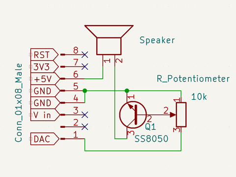
トランジスタのことよく分かっていない、データシート読めない私が作ったので間違っていると思うけど、ごめんなさい。でも動いた。
シールドはこんな感じ。
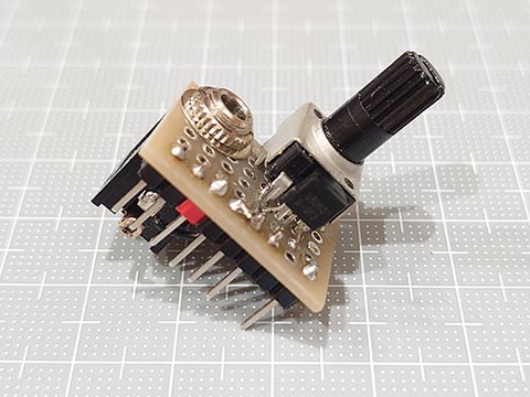
一列をさらに部分的にしか使っていないのでシールドと言っていいかも微妙ですが。
工夫した点は、UNO R4の平らな部分にジャックの底があたるようにすることで、高さ的にはピン+ピンソケットとほぼ同じ高さになりこころもち安定します。
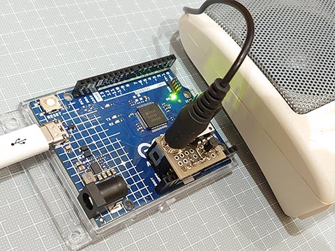
ボリュームを絞りすぎると音が出ず。開きすぎても音が出ず。
ちょうどいいところに持っていくと、まあまあ大きな音になります。
スピーカーでそこそこの音量での再生にチャレンジ。
使用したのは、10kΩの可変抵抗とNPNトランジスタと3.5mmジャック。
スピーカーは100円ショップで以前に購入したもの(アンプなし)。
回路図は以下のとおり。
トランジスタのことよく分かっていない、データシート読めない私が作ったので間違っていると思うけど、ごめんなさい。でも動いた。
シールドはこんな感じ。
一列をさらに部分的にしか使っていないのでシールドと言っていいかも微妙ですが。
工夫した点は、UNO R4の平らな部分にジャックの底があたるようにすることで、高さ的にはピン+ピンソケットとほぼ同じ高さになりこころもち安定します。
ボリュームを絞りすぎると音が出ず。開きすぎても音が出ず。
ちょうどいいところに持っていくと、まあまあ大きな音になります。
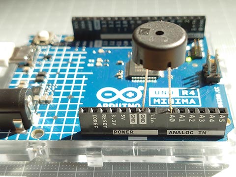
UNO R4 で WAVファイルを再生する [Arduino]
UNOでDACが使えることが分かったので、これを使って音声を再生してみました。
ファイル形式は、モノラル 8ビットのシンプルなwavファイルのみ。
<音源の準備>
・google翻訳の音声をmp3ファイルに変換してくれるサイトからゲット。
・これを Audacity を使って、モノラルの unsigned 8bit のwavファイルに変換。
・PROGMEM作蔵さん でC言語の配列に変換。(PROGMEMでなくてもいい)
バイナリファイルをC言語のデータ配列に変換する:放課後マイコンクラブ:SSブログ
https://hello-world.blog.ss-blog.jp/2016-10-16
スケッチは以下のとおりです。
レジスタ操作なしの純粋なArduinoスケッチで仕上げました。
AVRと違いピンのドライブ能力が高くないようで、直接スピーカーをつなげてもうまく音がでませんでした。
圧電サウンダだとかなり小さい音ですが、きれいに聞こえました。
音声データはこんな感じ(略しています)
ファイル形式は、モノラル 8ビットのシンプルなwavファイルのみ。
<音源の準備>
・google翻訳の音声をmp3ファイルに変換してくれるサイトからゲット。
・これを Audacity を使って、モノラルの unsigned 8bit のwavファイルに変換。
・PROGMEM作蔵さん でC言語の配列に変換。(PROGMEMでなくてもいい)
バイナリファイルをC言語のデータ配列に変換する:放課後マイコンクラブ:SSブログ
https://hello-world.blog.ss-blog.jp/2016-10-16
スケッチは以下のとおりです。
レジスタ操作なしの純粋なArduinoスケッチで仕上げました。
AVRと違いピンのドライブ能力が高くないようで、直接スピーカーをつなげてもうまく音がでませんでした。
圧電サウンダだとかなり小さい音ですが、きれいに聞こえました。
#include "hw8k.h"                               // wave file data

void setup() {
  analogWriteResolution(8);
}

void loop() {
  playWav( hw8k_en );
  delay(500);
  playWav( hw8k_ja );
  delay(500);
}

void playWav( const uint8_t d[] ) {             // monoral 8bit only
  uint32_t i, rate, len, usInt, usExp;
  rate  = *(uint32_t*)(&d[ 0x18 ]);             // Sampling rate
  len   = *(uint32_t*)(&d[ 0x28 ]);             // Data size
  usInt = 1000000 / rate;                       // Time interval
  usExp = micros();
  for( i = 0x2c; i < len; i++ ) {
      analogWrite( DAC, d[ i ] );
      while( micros() - usExp < usInt );
      usExp = micros();
  }
}
音声データはこんな感じ(略しています)
const uint8_t hw8k_ja[] = {    // file size : 13100 bytes
  0x52,0x49,0x46,0x46,0x24,0x33,0x00,0x00,0x57,0x41,0x56,0x45,0x66,0x6d,0x74,0x20,
  0x10,0x00,0x00,0x00,0x01,0x00,0x01,0x00,0x40,0x1f,0x00,0x00,0x40,0x1f,0x00,0x00,
  0x01,0x00,0x08,0x00,0x64,0x61,0x74,0x61,0x00,0x33,0x00,0x00,0x80,0x7f,0x80,0x80,
  0x7f,0x80,0x7f,0x80,0x7f,0x80,0x7f,0x80,0x7f,0x80,0x7f,0x80,0x7f,0x80,0x7f,0x80,
        ......
  0x7f,0x80,0x80,0x7f,0x80,0x7f,0x80,0x7f,0x80,0x80,0x80,0x7f
};

const uint8_t hw8k_en[] = {    // file size : 10220 bytes
  0x52,0x49,0x46,0x46,0xe4,0x27,0x00,0x00,0x57,0x41,0x56,0x45,0x66,0x6d,0x74,0x20,
  0x10,0x00,0x00,0x00,0x01,0x00,0x01,0x00,0x40,0x1f,0x00,0x00,0x40,0x1f,0x00,0x00,
  0x01,0x00,0x08,0x00,0x64,0x61,0x74,0x61,0xc0,0x27,0x00,0x00,0x80,0x80,0x80,0x80,
  0x80,0x80,0x80,0x80,0x80,0x80,0x80,0x80,0x80,0x80,0x80,0x80,0x80,0x80,0x80,0x7f,
        ......
  0x7f,0x80,0x80,0x80,0x7f,0x80,0x7f,0x80,0x7f,0x80,0x7f,0x80
};
UNO R4 の DAC について調べてみた。 [Arduino]
Arduino UNO R4 には、DAC (Digital Analog Converter) がついています。
アナログのA0ピンです。
デジタルでいうと14ピン。
UNO R4だと、定数で DAC および A0 が 14 となっていました。
どうやって出力するかというと、analogWrite を使うだけ。
analogWrite( ピン番号 , 値 );
でいい。
値は、
analogWriteResolution( 分解能(ビット数)) ;
で指定した範囲。
これを指定しない場合はデフォルトの8になるので、0-255の範囲。12を指定すると0-4095の範囲。
// UNO R4 DAC analogWrite

void setup() {
  analogWriteResolution( 12 );  // If not specified, the default is 8.
}

void loop() {
  static uint16_t val;
  val = ++val & 0x0fff;         // 0, 1, 2, ..., 4095 , 0, 1, 2, ...
  analogWrite( DAC, val );
  delayMicroseconds( 500 );
}
ピン番号がDAC対応ピン(DAC/A0/D14)だとDACで出力し、非対応ピンの場合にはPWMで出力するようになっています。13番ピン(LED_BUILTIN)にすると、PWMで内臓LEDが光ります。
DACピンでの analogWrite() は呼び出されると、大まかに以下の手順。
1. ピンがDAC使用可能ピンか確認
2. DACのチャンネル取得?
3. dac.cppのanalogWriteに値を渡す
4. 値を分解能に合わせてスケーリング
5. 値を書き込む
という手順です。
%localAppData%\Arduino15\packages\arduino\hardware\renesas_uno\1.0.4\cores\arduino
(1.0.4のところはバージョンによって異なります。)
ここの dac.cpp や analog.cpp を参照。
1, 2の作業を毎回ではなく、先にしておいて、3~5だけを行うのが以下のスケッチ。
少し早くなります。(delayMicroseconds()をなくすとよくわかります。)
// UNO R4 DAC analogWrite (faster)

#include <dac.h>

static CDac dac( A0 );

void setup() {
  analogWriteResolution( 12 );  // If not specified, the default is 8.
}

void loop() {
  static uint16_t val;
  val = ++val & 0x0fff;         // 12bit : 0, 1, 2, ..., 4095 , 0, 1, 2, ...
  dac.analogWrite( val );       // faster
  delayMicroseconds( 500 );
}
これでいいのかどうかはわからないけど、とりあえず動いている。
analogWrite()のかわりに、init()とset()だけでいけると思ったけど、だめだった。
さらに、レジスタをいじってみる。(5の作業のみ。)
// UNO R4 DAC analogWrite (fastest)

void setup() {
  analogWriteResolution( 12 );  // If not specified, the default is 8.
  analogWrite( DAC, 0 );        // For initialization.
}

void loop() {
  static uint16_t val;
  val = ++val & 0x0fff;         // 12bit : 0, 1, 2, ... , 4095, 0, 1, 2, ...
  R_DAC->DADR[0] = val;
  delayMicroseconds( 500 );
}
DACの初期設定もレジスタをいじるのは大変なので、analogWrite( DAC, 0 ); を1回呼び出すことで代用。
処理速度は断然速いです。
(delayMicroseconds()を外して書き込み、UNO R4を振ると残像の細かさがダントツです。)
(LEDの明るさで動作確認をしたけど、LEDは一定の電圧以下では光らないので、LEDの明るさ調整にはPWMのほうが向いていそう。)
CH552 で リモコン信号をシリアル送信 [Arduino]
CH552にも移植してみました。
Ch55xduinoで注意が必要なのは、、
・C++ではなくCである
・pulseIn()がない
・シリアル通信がいつものと異なる
pulseIn()については、100μ秒オーダー程度の精度で十分なので、micros()で自作。
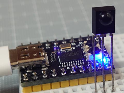
ちなみに、CH552 のピン P1.0~P1.7, P3.0~P3.7 のうち、CH552 mini coreでは、P1.2, P1.3 は外部クリスタル、P3.6, P3.7 はそれぞれUDP, UDMで、USBとつながっているためI/Oピンには使えません。
ちょっとこれで嵌りました。
Ch55xduinoで注意が必要なのは、、
・C++ではなくCである
・pulseIn()がない
・シリアル通信がいつものと異なる
pulseIn()については、100μ秒オーダー程度の精度で十分なので、micros()で自作。
// IR Receive and Decode (CH55x ver.)

#define IR_IN    11          // IR Receiver pin

uint32_t pulseIn(uint8_t pin, uint8_t state, uint32_t timeout) {
    uint32_t  usExp = micros();
    while( digitalRead( pin ) == state )  if( micros() - usExp > timeout ) return 0;
    while( digitalRead( pin ) != state )  if( micros() - usExp > timeout ) return 0;
    uint32_t  usOrg = micros();
    while( digitalRead( pin ) == state )  if( micros() - usExp > timeout ) return 0;
    return micros() - usOrg;
}

void setup() {
  pinMode( IR_IN , INPUT );                     // input  Vout(active low, negative logic)
  pinMode(  31 ,  OUTPUT ); digitalWrite( 31, LOW  );   // LOW  (*use as GND)
  pinMode(  30 ,  OUTPUT ); digitalWrite( 30, HIGH );   // HIGH (*use as Vcc)
}

void loop() {
  uint32_t  irData = 0;
  uint8_t   irProtocol = 0, irBit = 0;
  __xdata uint8_t   irArray[20] = {0};

  // ****** Receive and Decode IR signals ******
  uint16_t  us = pulseIn( IR_IN, LOW , 65535 ); // Judge the protocol by the length of the leader section (usec.)
  if      ( us > 2000 && us <  3000 ) {         //  *** SIRC ***
      irProtocol = 'S';                         //  T=600us, ON/OFF : leader= 4T/1T, 0=1T/1T, 1=2T/1T
      for(;(us = pulseIn( IR_IN, LOW , 3000 )); irBit++)
        if( us > 1000 && us <  1500 ) irData |= (1UL << irBit);
  }else if( us > 3500 && us <  5000 ) {         //  *** AEHA ***
      irProtocol = 'A';                         //  T=425us, ON/OFF : leader= 8T/4T, 0=1T/1T, 1=1T/3T, stop=1T
      while( digitalRead( IR_IN ) );
      for(;(us = pulseIn( IR_IN, HIGH, 4000 )); irBit++)
        if( us > 1050 && us <  1500 ) irArray[ irBit / 8 ] |= (1 << (irBit % 8) );
  }else if( us > 7200 && us < 11000 ) {         //  *** NEC ***
      irProtocol = 'N';                         //  T=560us, ON/OFF : leader=16T/8T, 0=1T/1T, 1=1T/3T, stop=1T
      while( digitalRead( IR_IN ) );
      for(;(us = pulseIn( IR_IN, HIGH, 3000 )); irBit++)
        if( us > 1350 && us <  2000 ) irData |= (1UL << irBit);
  }else return;

  // ****** Display results by protocol ******
  USBSerial_print( irProtocol == 'S' ? "SIRC: " : irProtocol == 'A' ? "AEHA: " : "NEC : " );
  if( !irBit ) {
    USBSerial_println( " (repeat code) " );
    return;
  }
  USBSerial_print( irBit );
  USBSerial_print( "bit" );
  if( irProtocol == 'A' ) {
    for( uint8_t i = 0; i < ( (irBit + 7) / 8 ); i++ ) {
      USBSerial_print((irArray[i] < 0x10) ? " 0x0" : " 0x" );
      USBSerial_print( irArray[i], HEX );
    }
  } else {
      USBSerial_print( " 0x" );
      USBSerial_print( irData, HEX );
      USBSerial_print( "\t0b" );
      USBSerial_print( irData, BIN );
  }
  USBSerial_println("");
}
ちなみに、CH552 のピン P1.0~P1.7, P3.0~P3.7 のうち、CH552 mini coreでは、P1.2, P1.3 は外部クリスタル、P3.6, P3.7 はそれぞれUDP, UDMで、USBとつながっているためI/Oピンには使えません。
ちょっとこれで嵌りました。


