202duino の SPI で NeoPixel [Arduino]
NTSCビデオ信号のドット幅がなかなかそろわず、SPIに手を出そうと、、。
SPIでデータを送る練習としてNeoPixelで実験。
以前に作ったのと同様にNeoPixel棒を光らせられました。
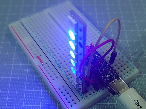
202duino で NeoPixel [Arduino]
https://hello-world.blog.ss-blog.jp/2023-07-15
スケッチサイズは582バイトと軽量に。
WS2812Bのデータシートには、
Data transfar Time
0 : High 220- 380ns / Low 580-1000ns
1 : High 580-1000ns / Low 580-1000ns
ってあるけと、どうやら Highの時間の長短で0/1を決めているみたいで、Lowの時間は厳密に守らなくてもいいみたい。
問題点は、ATtiny202は実質の有効ピンが5ピンにも関わらず、SPIを使うと、MOSIの他、MISO、SCK も使ってしまうので、他に使える残りのピンが2本になってしまい、あまり実用的ではないかも。
というわけで、NTSCビデオ計画はちょっと保留。
SPIでデータを送る練習としてNeoPixelで実験。
以前に作ったのと同様にNeoPixel棒を光らせられました。
202duino で NeoPixel [Arduino]
https://hello-world.blog.ss-blog.jp/2023-07-15
スケッチサイズは582バイトと軽量に。
// ATtiny202 SPI NeoPixel test (20MHz)

#define T0        (0b11100000)  // T0H : 300ns @ 20MHz CLK2X DIV4
#define T1        (0b11111100)  // T1H : 600ns @ 20MHz CLK2X DIV4
#define NUMPIXELS (12)

uint8_t pixels[NUMPIXELS * 3];  // GRBGRBGRB...

void setup() {
  PORTA.DIRSET = _BV(1);        // PA1(MOSI) OUTPUT (megaTinyCore:D2)
  SPI0.CTRLA   = SPI_MASTER_bm | SPI_CLK2X_bm | SPI_PRESC_DIV4_gc | SPI_ENABLE_bm;
  SPI0.CTRLB   = SPI_BUFEN_bm | SPI_BUFWR_bm | SPI_SSD_bm | SPI_MODE_1_gc;
}

void loop() {
  for (uint8_t i = 0; i < NUMPIXELS; i++) {
    for (uint8_t c = 0; c < 6; c++) {
        pixels[ ((NUMPIXELS + i - c) * 3 + 2) % (NUMPIXELS * 3) ] = 31 >> c;
    }
    neoPixelShow();
    delay(100);
  }
}

void neoPixelShow() {
  for(uint8_t i = 0; i < NUMPIXELS * 3; i++) {
    for(uint8_t bm = 0b10000000; bm; bm >>= 1) {
      SPI0.DATA = (pixels[i] & bm) ? T1 : T0;
      while( !(SPI0.INTFLAGS & SPI_DREIF_bm) );
    }
  }
}
WS2812Bのデータシートには、
Data transfar Time
0 : High 220- 380ns / Low 580-1000ns
1 : High 580-1000ns / Low 580-1000ns
ってあるけと、どうやら Highの時間の長短で0/1を決めているみたいで、Lowの時間は厳密に守らなくてもいいみたい。
問題点は、ATtiny202は実質の有効ピンが5ピンにも関わらず、SPIを使うと、MOSIの他、MISO、SCK も使ってしまうので、他に使える残りのピンが2本になってしまい、あまり実用的ではないかも。
というわけで、NTSCビデオ計画はちょっと保留。
ATtiny412でNTSCビデオ信号 [Arduino]
NTSCでのビデオ出力。
いろいろ調べてみたけど、結構たいへん。
1.情報収集
小さなカラーLCDなども安価になってきていて、いまどきマイコンでNTSCでのビデオ出力する人が少なくなっている。記事をさぐると10年くらい前のものが多く、リンク切れも多数。
カラー、ノンインターレスの説明は見つかるものの、基本のモノクロとノンインターレスの情報が少なめ。PICでの情報が多めな感じ。
2.ソフトウェア
全部あるいは部分的にアセンブラを使わないといけなかったり、SPIを出力につかったり。
とくにカラーは超高難度のよう。
別ICと組み合わせが必要なものも。
3.ハードウェア
簡単なものだと同期信号と画像信号と2本の抵抗を介して出力。
外部クロックを使用しないと画像が揺らぐらしい。
そこで、C言語だけで、tinyAVR 1シリーズのDAC機能を使って、コネクタ以外の外付けパーツなしでビデオ出力できるかやってみました。
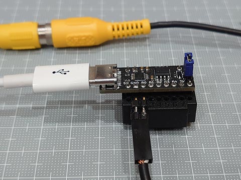
とりあえずできたけど、ウェイトなしで横16ドットしか表示できていない。
もうちょっとなんとかなりそうな気もする。

[2023/11/02]
その後、ちょっと改善
・割り算をなくした
・16ビットでなくてもいい変数は8ビットに
・データを1ドットあたり1byte → 1bitとした
・for文を使わず、配列の添え字を変数にせず、すべて展開
(横1ドットにつきプログラム1行)
などで、横128ドットまでは行きついた。
同期をなんとかせねば。

[2023/11/03]
ジッター(揺らぎ)の原因がプログラムの問題なのか、クリスタルの有無の問題なのか、SYNCとVIDEOと2本の抵抗を使ってATmega328のArduinoに移植してみた。
1ドット毎の幅が違うから右端がそろわないけど、くっきりになった。

やっぱりクリスタルがないとダメってことか。
[2023/11/03]
いろいろ修正しながらATtint202でやってみた。
ジッター(揺らぎ)はあるものの、くっきりはした。エッジがぼやけるのはDACのせいだったらしい。

もうちょっと形になったらブログに上げたい。
いろいろ調べてみたけど、結構たいへん。
1.情報収集
小さなカラーLCDなども安価になってきていて、いまどきマイコンでNTSCでのビデオ出力する人が少なくなっている。記事をさぐると10年くらい前のものが多く、リンク切れも多数。
カラー、ノンインターレスの説明は見つかるものの、基本のモノクロとノンインターレスの情報が少なめ。PICでの情報が多めな感じ。
2.ソフトウェア
全部あるいは部分的にアセンブラを使わないといけなかったり、SPIを出力につかったり。
とくにカラーは超高難度のよう。
別ICと組み合わせが必要なものも。
3.ハードウェア
簡単なものだと同期信号と画像信号と2本の抵抗を介して出力。
外部クロックを使用しないと画像が揺らぐらしい。
そこで、C言語だけで、tinyAVR 1シリーズのDAC機能を使って、コネクタ以外の外付けパーツなしでビデオ出力できるかやってみました。

とりあえずできたけど、ウェイトなしで横16ドットしか表示できていない。
もうちょっとなんとかなりそうな気もする。

// ATtiny412 NTSC test (20MHz)
#define   IRE_p100  (59)        // = 255 * 1.0V/4.34V * (40+100)/140
#define   IRE_p50   (38)        // = 255 * 1.0V/4.34V * (40+ 50)/140
#define   IRE_0     (17)        // = 255 * 1.0V/4.34V *  40     /140
#define   IRE_m40   (0)

uint8_t const img_i[] = {
  0,0,0,0,0,0,0,0,0,1,1,0,0,0,0,0,
  0,0,0,0,0,0,0,0,0,0,1,1,0,0,0,0,
  0,0,0,0,0,0,0,0,0,0,1,1,1,0,0,0,
  0,0,0,0,0,0,0,0,0,1,1,1,0,0,0,0,
  0,0,0,0,0,0,0,0,1,1,1,0,0,0,0,0,
  0,0,0,0,0,0,0,0,1,1,0,0,0,0,0,0,
  0,0,0,0,0,0,0,1,1,1,0,0,0,0,0,0,
  0,0,0,0,0,0,1,1,0,1,1,0,0,0,0,0,
  0,0,0,0,1,1,1,0,0,1,1,0,0,0,0,0,
  0,0,0,1,1,0,0,0,0,1,1,0,0,0,0,0,
  0,1,1,0,0,0,0,0,0,1,1,0,0,0,0,0,
  0,0,0,0,0,0,0,0,0,1,1,0,0,0,0,0,
  0,0,0,0,0,0,0,0,0,1,1,0,0,0,0,0,
  0,0,0,0,0,0,0,0,1,1,1,0,0,0,0,0,
  0,0,0,0,0,0,0,0,1,1,1,0,0,0,0,0,
  0,0,0,0,0,0,0,0,0,1,1,0,0,0,0,0,
  0,0,0,0,0,0,0,0,0,0,0,0,0,0,0,0
};

void setup(){                           // Register Settings
  // VIDEO OUTPUT
    VREF.CTRLA |= VREF_DAC0REFSEL_4V34_gc;              // Voltage reference at 4.34V
    VREF.CTRLB |= VREF_DAC0REFEN_bm;                    // DAC0/AC0 reference enable: enabled
    delayMicroseconds(25);                              // Wait VREF start-up time
    PORTA.PIN6CTRL &= ~PORT_ISC_gm;                     // Disable digital input buffer
    PORTA.PIN6CTRL |=  PORT_ISC_INPUT_DISABLE_gc;
    PORTA.PIN6CTRL &= ~PORT_PULLUPEN_bm;                // Disable pull-up resistor
    DAC0.CTRLA = DAC_ENABLE_bm | DAC_OUTEN_bm;          // Enable DAC, Output Buffer
  // H-SYNC
    TCB0.CTRLA  = TCB_CLKSEL_CLKDIV1_gc | TCB_ENABLE_bm;// 20MHz / 1 / 1270 -> 15,750Hz
    TCB0.CTRLB  = TCB_CNTMODE_INT_gc;                   // periodic Interrupt mode
    TCB0_CCMP   = 1269;                                 // top value
    TCB0.INTCTRL= TCB_CAPT_bm;                          // Capture Interrupt Enable
}

void loop() {
}

ISR(TCB0_INT_vect) {
  static uint16_t scan, x, y, offset;
  DAC0.DATA = IRE_0;                                    // start from -3.2usec
  scan++;
  while(TCB0_CNT <  94);                                // front porch (20MHz*(3.2+1.5    )usec=94)
  DAC0.DATA = IRE_m40;
  if(scan > 3  && scan < 7)   goto END;
  while(TCB0_CNT < 188);                                // back porch  (20MHz*(3.2+1.5+4.7)usec=188)
  DAC0.DATA = IRE_0;
  if(scan < 48 || scan > 239) goto END;                 // 192 lines
  y = (scan - 48) / 12;                                 // y = 0..15
  offset= y<<4;
  while(TCB0_CNT < 282);                                // H-blanking  (20MHz*(3.2+10.9   )usec=282)
  MAIN:
  for(x=0; x<16; x++) {
    DAC0.DATA = (img_i[x + offset]) ? IRE_p100 : IRE_0;
  }
  DAC0.DATA = IRE_0;
  END:
  if(scan == 262) scan = 0;
  TCB0.INTFLAGS= TCB_CAPT_bm;                           // Clear Capture Interrupt Flag
}
[2023/11/02]
その後、ちょっと改善
・割り算をなくした
・16ビットでなくてもいい変数は8ビットに
・データを1ドットあたり1byte → 1bitとした
・for文を使わず、配列の添え字を変数にせず、すべて展開
(横1ドットにつきプログラム1行)
などで、横128ドットまでは行きついた。
同期をなんとかせねば。

[2023/11/03]
ジッター(揺らぎ)の原因がプログラムの問題なのか、クリスタルの有無の問題なのか、SYNCとVIDEOと2本の抵抗を使ってATmega328のArduinoに移植してみた。
1ドット毎の幅が違うから右端がそろわないけど、くっきりになった。

やっぱりクリスタルがないとダメってことか。
[2023/11/03]
いろいろ修正しながらATtint202でやってみた。
ジッター(揺らぎ)はあるものの、くっきりはした。エッジがぼやけるのはDACのせいだったらしい。

もうちょっと形になったらブログに上げたい。
I2C OLED (SSD1306)に画像を出す。Wire版 [Arduino]
Wireライブラリー + delay() を使って一般的なArduinoでだいたい動くようにしました。
・ATtiny 412 (megaTinyCore)
・UNO R1 (ATmega328)
・UNO R4 MINIMA (RA4M1)
・RL78/G15 Fast Prototyping Board
で動くことを確認しました。
ATyiny202には 2269バイトとフラッシュメモリ 2kByteをオーバーしてしまい不可でした。
こんな感じで、、
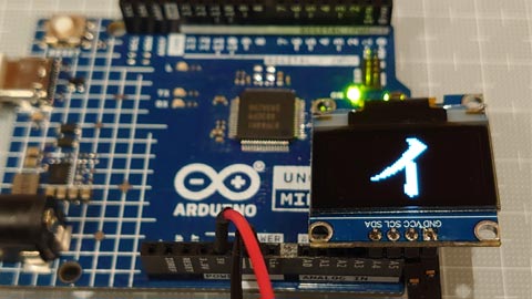
ブレッドボードなしでつないでみた。
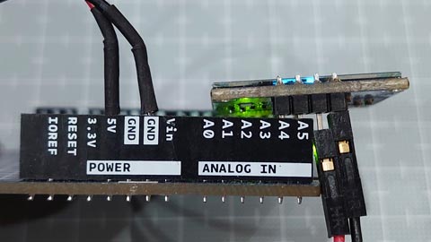
・ATtiny 412 (megaTinyCore)
・UNO R1 (ATmega328)
・UNO R4 MINIMA (RA4M1)
・RL78/G15 Fast Prototyping Board
で動くことを確認しました。
ATyiny202には 2269バイトとフラッシュメモリ 2kByteをオーバーしてしまい不可でした。
こんな感じで、、

ブレッドボードなしでつないでみた。

// tinyOLEDdemo - controlling an I²C OLED (SSD1306)
#include <Wire.h>

uint8_t const img_i[] = {   32,   32, // px
  0x00, 0x00, 0x00, 0x00, 0x00, 0x00, 0x00, 0x00, 0x00, 0x00, 0x00, 0x00, 0x00, 0x00, 0x00, 0x00,
  0x00, 0x00, 0x00, 0x82, 0xee, 0xfe, 0xfe, 0xfc, 0xf8, 0x70, 0x20, 0x00, 0x00, 0x00, 0x00, 0x00,
  0x00, 0x00, 0x00, 0x00, 0x00, 0x00, 0x00, 0x00, 0x00, 0x00, 0x00, 0x00, 0x80, 0xc0, 0xe0, 0xf0,
  0xf8, 0x7e, 0xff, 0xff, 0xef, 0xc7, 0x03, 0x01, 0x00, 0x00, 0x00, 0x00, 0x00, 0x00, 0x00, 0x00,
  0x00, 0x00, 0x00, 0x20, 0x20, 0x30, 0x10, 0x18, 0x1c, 0x0e, 0x0f, 0x07, 0x07, 0x03, 0x01, 0x01,
  0x00, 0x00, 0xff, 0xff, 0xff, 0xff, 0x00, 0x00, 0x00, 0x00, 0x00, 0x00, 0x00, 0x00, 0x00, 0x00,
  0x00, 0x00, 0x00, 0x00, 0x00, 0x00, 0x00, 0x00, 0x00, 0x00, 0x00, 0x00, 0x00, 0x00, 0x00, 0x00,
  0x00, 0x1e, 0x3f, 0x7f, 0x3f, 0x3f, 0x00, 0x00, 0x00, 0x00, 0x00, 0x00, 0x00, 0x00, 0x00, 0x00
};
uint8_t const img_qr[] = {  23,   23, // px
  0xff, 0x01, 0x7d, 0x45, 0x45, 0x45, 0x7d, 0x01, 0xff, 0x2b, 0xcb, 0x71, 0xdf, 0x01, 0xff, 0x01,
  0x7d, 0x45, 0x45, 0x45, 0x7d, 0x01, 0xff, 0xff, 0x59, 0x55, 0x7d, 0x71, 0x49, 0x67, 0x55, 0xf9,
  0x3d, 0xc2, 0x8b, 0x57, 0x91, 0x3d, 0x77, 0xc9, 0x27, 0xb9, 0x93, 0x71, 0xf7, 0xff, 0xff, 0xc0,
  0xdf, 0xd1, 0xd1, 0xd1, 0xdf, 0xc0, 0xff, 0xc1, 0xf3, 0xfa, 0xcd, 0xd5, 0xc8, 0xc5, 0xea, 0xe6,
  0xe8, 0xd8, 0xcb, 0xec, 0xff
};

// ---- OLED Implementation ----------------------------------------------------

#define OLED_ADDR       0x3c             // OLED write address (Wire lib.:0x3c)
#define OLED_CMD_MODE   0x00             // set command mode
#define OLED_DAT_MODE   0x40             // set data mode

const uint8_t OLED_INIT_CMD[] = {        // OLED init settings
  0xA8, 0x3F,           // set multiplex (HEIGHT-1): 0x1F for 128x32, 0x3F for 128x64
  0x22, 0x00, 0x07,     // set min and max page
  0x20, 0x00,           // set horizontal memory addressing mode
  0xDA, 0x12,           // set COM pins hardware configuration to alternative
  0x8D, 0x14,           // enable charge pump
  0xAF                  // switch on OLED
};

void OLED_init(void) {                    // OLED init function
  Wire.begin();                           //   initialize I2C first
  Wire.beginTransmission(OLED_ADDR);      //   start transmission to OLED
  Wire.write(OLED_CMD_MODE);              //   set command mode
  for (uint8_t i=0; i<sizeof(OLED_INIT_CMD); i++) Wire.write(OLED_INIT_CMD[i]); // send the command bytes
  Wire.endTransmission();                 //   stop transmission
}

void OLED_cursor(uint8_t xpos, uint8_t ypos) {// OLED set the cursor
  Wire.beginTransmission(OLED_ADDR);      //   start transmission to OLED
  Wire.write(OLED_CMD_MODE);              //   set command mode
  Wire.write(xpos & 0x0F);                //   set low nibble of start column
  Wire.write(0x10 | (xpos >> 4));         //   set high nibble of start column
  Wire.write(0xB0 | (ypos & 0x07));       //   set start page
  Wire.endTransmission();                 //   stop transmission
}

void OLED_clear(uint8_t p) {              // OLED clear screen with pattern
  OLED_cursor(0, 0);                      //   set cursor at upper left corner
  for(uint8_t j=1024/16; j; j--) {
    Wire.beginTransmission(OLED_ADDR);    //   start transmission to OLED
    Wire.write(OLED_DAT_MODE);            //   set data mode
    for(uint8_t i=16; i; i--) Wire.write(p);// clear the screen with p
    Wire.endTransmission();               //   stop transmission
  }
}

void OLED_image(uint8_t xpos, uint8_t ypos, const uint8_t *d) {// OLED set image
  const uint8_t w=*d++, h=*d++;
  for(uint8_t y=0, i=0; y<(h+7)/8; y++) {
    OLED_cursor(xpos, ypos + y);          //   set the cursor
    for(uint8_t x=0; x<w; x++) {
      if( !i ) {
        Wire.beginTransmission(OLED_ADDR);//   start transmission to OLED
        Wire.write(OLED_DAT_MODE);        //   set data mode
      }
      Wire.write( *d++ );
      if( ++i==31 || w-x==1 ) {
        Wire.endTransmission();           //   stop transmission
        i=0;
      }
    }
  }
}

void OLED_image2x(uint8_t xpos, uint8_t ypos, const uint8_t *d) {// OLED set 2x image
  const uint8_t x2[]={ 0x0,0x3,0xc,0xf,0x30,0x33,0x3c,0x3f,0xc0,0xc3,0xcc,0xcf,0xf0,0xf3,0xfc,0xff };
  const uint8_t w=*d++, h=*d++;
  for(uint8_t y=0, i=0; y<(h+3)/4; y++) {
    OLED_cursor(xpos, ypos + y);          //   set the cursor
    for(uint8_t x=0, t; x<w; x++) {
      if( !i ) {
        Wire.beginTransmission(OLED_ADDR);//   start transmission to OLED
        Wire.write(OLED_DAT_MODE);        //   set data mode
      }
      Wire.write( t = x2[ d[x+(y/2)*w] >> (y%2*4) & 0xf ] );
      Wire.write( t );
      if( (i+=2)>29 || w-x==1 ) {
        Wire.endTransmission();           //   stop transmission
        i=0;
      }
    }
  }
}

// ---- Main Function ----------------------------------------------------------

void setup() {
  delay(100);                             // add delay
  OLED_init();                            // setup I2C OLED
}

void loop() {
  OLED_clear(0x00);                       // clear screen with black
  OLED_image( 48, 2, img_i );
  delay(1000);
  OLED_image2x( 32, 0, img_i );
  delay(2000);
  OLED_clear(0xff);                       // clear screen with white
  OLED_image( 52, 2, img_qr );
  delay(1000);
  OLED_image2x( 40, 1, img_qr );
  delay(4000);
}
I2C OLED (SSD1306)に画像を出す。ATtiny202版 [Arduino]
ATtiny202でI2C OLEDに画像を出すスケッチをつくってみた。
GitHub - wagiminator_ATtiny13-TinyOLEDdemo I²C OLED on an ATtiny10_13_202
https://github.com/wagiminator/ATtiny13-TinyOLEDdemo
これを参考に、、といっても、データを流すだけで画像が出るようにデータ配列に変換してあるので大したことはしてません。
そこで、2倍に拡大した画像も出せるようにしてみました。
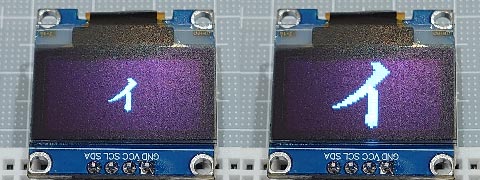
ややジャギーが気になるけど、、
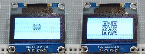
QRコードなら問題なし。
スケッチも1247バイトと軽量。
GitHub - wagiminator_ATtiny13-TinyOLEDdemo I²C OLED on an ATtiny10_13_202
https://github.com/wagiminator/ATtiny13-TinyOLEDdemo
これを参考に、、といっても、データを流すだけで画像が出るようにデータ配列に変換してあるので大したことはしてません。
そこで、2倍に拡大した画像も出せるようにしてみました。

ややジャギーが気になるけど、、

QRコードなら問題なし。
スケッチも1247バイトと軽量。
// tinyOLEDdemo - controlling an I²C OLED (SSD1306) with an ATtiny202
//
// A big thank you to Stefan Wagner
// Project Files (Github):  https://github.com/wagiminator
// License: http://creativecommons.org/licenses/by-sa/3.0/

#include <avr/io.h>
#include <util/delay.h>

const uint8_t img_i[] = {   32,   32, // px
  0x00, 0x00, 0x00, 0x00, 0x00, 0x00, 0x00, 0x00, 0x00, 0x00, 0x00, 0x00, 0x00, 0x00, 0x00, 0x00,
  0x00, 0x00, 0x00, 0x82, 0xee, 0xfe, 0xfe, 0xfc, 0xf8, 0x70, 0x20, 0x00, 0x00, 0x00, 0x00, 0x00,
  0x00, 0x00, 0x00, 0x00, 0x00, 0x00, 0x00, 0x00, 0x00, 0x00, 0x00, 0x00, 0x80, 0xc0, 0xe0, 0xf0,
  0xf8, 0x7e, 0xff, 0xff, 0xef, 0xc7, 0x03, 0x01, 0x00, 0x00, 0x00, 0x00, 0x00, 0x00, 0x00, 0x00,
  0x00, 0x00, 0x00, 0x20, 0x20, 0x30, 0x10, 0x18, 0x1c, 0x0e, 0x0f, 0x07, 0x07, 0x03, 0x01, 0x01,
  0x00, 0x00, 0xff, 0xff, 0xff, 0xff, 0x00, 0x00, 0x00, 0x00, 0x00, 0x00, 0x00, 0x00, 0x00, 0x00,
  0x00, 0x00, 0x00, 0x00, 0x00, 0x00, 0x00, 0x00, 0x00, 0x00, 0x00, 0x00, 0x00, 0x00, 0x00, 0x00,
  0x00, 0x1e, 0x3f, 0x7f, 0x3f, 0x3f, 0x00, 0x00, 0x00, 0x00, 0x00, 0x00, 0x00, 0x00, 0x00, 0x00
};
const uint8_t img_qr[] = {  23,   23, // px
  0xff, 0x01, 0x7d, 0x45, 0x45, 0x45, 0x7d, 0x01, 0xff, 0x2b, 0xcb, 0x71, 0xdf, 0x01, 0xff, 0x01,
  0x7d, 0x45, 0x45, 0x45, 0x7d, 0x01, 0xff, 0xff, 0x59, 0x55, 0x7d, 0x71, 0x49, 0x67, 0x55, 0xf9,
  0x3d, 0xc2, 0x8b, 0x57, 0x91, 0x3d, 0x77, 0xc9, 0x27, 0xb9, 0x93, 0x71, 0xf7, 0xff, 0xff, 0xc0,
  0xdf, 0xd1, 0xd1, 0xd1, 0xdf, 0xc0, 0xff, 0xc1, 0xf3, 0xfa, 0xcd, 0xd5, 0xc8, 0xc5, 0xea, 0xe6,
  0xe8, 0xd8, 0xcb, 0xec, 0xff
};
// ---- I2C Master Implementation (Write only) ---------------------------------

#define I2C_FREQ  800000UL                        // I2C clock frequency in Hz
void I2C_init(void) {                             // I2C init function
  TWI0.MBAUD   = ((F_CPU / I2C_FREQ) - 10) / 2;   //   set TWI master BAUD rate (simplified BAUD calculation)
  TWI0.MCTRLA  = TWI_ENABLE_bm;                   //   enable TWI master
  TWI0.MSTATUS = TWI_BUSSTATE_IDLE_gc;            //   set bus state to idle
}
void I2C_start(uint8_t addr) {                    // I2C start transmission
  TWI0.MADDR = addr;                              //   start sending address
}
void I2C_stop(void) {                             // I2C stop transmission
  while (~TWI0.MSTATUS & TWI_WIF_bm);             //   wait for last transfer to complete
  TWI0.MCTRLB = TWI_MCMD_STOP_gc;                 //   send stop condition
}
void I2C_write(uint8_t data) {                    // I2C transmit one data byte to the slave, ignore ACK bit
  while (~TWI0.MSTATUS & TWI_WIF_bm);             //   wait for last transfer to complete
  TWI0.MDATA = data;                              //   start sending data byte
}

// ---- OLED Implementation ----------------------------------------------------

#define OLED_ADDR       0x78             // OLED write address (Wire lib.:0x3c)
#define OLED_CMD_MODE   0x00             // set command mode
#define OLED_DAT_MODE   0x40             // set data mode

const uint8_t OLED_INIT_CMD[] = {        // OLED init settings
  0xA8, 0x3F,           // set multiplex (HEIGHT-1): 0x1F for 128x32, 0x3F for 128x64
  0x22, 0x00, 0x07,     // set min and max page
  0x20, 0x00,           // set horizontal memory addressing mode
  0xDA, 0x12,           // set COM pins hardware configuration to alternative
  0x8D, 0x14,           // enable charge pump
  0xAF                  // switch on OLED
};

void OLED_init(void) {                    // OLED init function
  I2C_init();                             //   initialize I2C first
  I2C_start(OLED_ADDR);                   //   start transmission to OLED
  I2C_write(OLED_CMD_MODE);               //   set command mode
  for (uint8_t i=0; i<sizeof(OLED_INIT_CMD); i++) I2C_write(OLED_INIT_CMD[i]); //   send the command bytes
  I2C_stop();                             //   stop transmission
}

void OLED_cursor(uint8_t xpos, uint8_t ypos) {// OLED set the cursor
  I2C_start(OLED_ADDR);                   //   start transmission to OLED
  I2C_write(OLED_CMD_MODE);               //   set command mode
  I2C_write(xpos & 0x0F);                 //   set low nibble of start column
  I2C_write(0x10 | (xpos >> 4));          //   set high nibble of start column
  I2C_write(0xB0 | (ypos & 0x07));        //   set start page
  I2C_stop();                             //   stop transmission
}

void OLED_clear(uint8_t p) {              // OLED clear screen with pattern
  OLED_cursor(0, 0);                      //   set cursor at upper left corner
  I2C_start(OLED_ADDR);                   //   start transmission to OLED
  I2C_write(OLED_DAT_MODE);               //   set data mode
  for(uint16_t i=1024; i; i--) I2C_write(p);  // clear the screen
  I2C_stop();                             //   stop transmission
}

void OLED_image(uint8_t xpos, uint8_t ypos, uint8_t *d) {// OLED set image
  const uint8_t w=*d++, h=*d++;
  for(uint8_t y=0; y<(h+7)/8; y++) {
    OLED_cursor(xpos, ypos + y);          //   set the cursor
    I2C_start(OLED_ADDR);                 //   start transmission to OLED
    I2C_write(OLED_DAT_MODE);             //   set data mode
    for(uint8_t x=0; x<w; x++) I2C_write( *d++ );
    I2C_stop();                           //   stop transmission
  }
}

void OLED_image2x(uint8_t xpos, uint8_t ypos, uint8_t *d) {// OLED set 2x image
  const uint8_t x2[]={ 0x0,0x3,0xc,0xf,0x30,0x33,0x3c,0x3f,0xc0,0xc3,0xcc,0xcf,0xf0,0xf3,0xfc,0xff };
  const uint8_t w=*d++, h=*d++;
  for(uint8_t y=0; y<(h+3)/4; y++) {
    OLED_cursor(xpos, ypos + y);          //   set the cursor
    I2C_start(OLED_ADDR);                 //   start transmission to OLED
    I2C_write(OLED_DAT_MODE);             //   set data mode
    for(uint8_t x=0, t; x<w; x++) {
      I2C_write( t = x2[ d[x+(y/2)*w] >> (y%2*4) & 0xf ] );
      I2C_write( t );
    }
    I2C_stop();                           //   stop transmission
  }
}

// ---- Main Function ----------------------------------------------------------

void setup() {
  _delay_ms(100);                         // add delay
  OLED_init();                            // setup I2C OLED
}

void loop() {
  OLED_clear(0x00);                       // clear screen with black
  OLED_image( 48, 2, img_i );
  _delay_ms(1000);
  OLED_image2x( 32, 0, img_i );
  _delay_ms(2000);
  OLED_clear(0xff);                       // clear screen with white
  OLED_image( 52, 2, img_qr );
  _delay_ms(1000);
  OLED_image2x( 41, 1, img_qr );
  _delay_ms(4000);
}
202duino で I2C OLEDディスプレイ [Arduino]
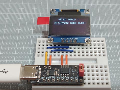
ちょっと前にAliexpressで買ったままになっていた I2C OLED ディスプレイを出してみた。
SSD1306という制御チップを使ったもの。
プルアップ抵抗なしでもなんとかなった。
ATtiny202で制御できるかどうか調べてみると、、ありました。
GitHub - wagiminator_ATtiny13-TinyOLEDdemo I²C OLED on an ATtiny10_13_202
https://github.com/wagiminator/ATtiny13-TinyOLEDdemo
ここで使われているのは、128 x 32 ドット用のスケッチなので、128 x 64 ドット用にちょっと変更するとふつうに使えました。
変更箇所の1つめは、
// OLED init settings
const uint8_t OLED_INIT_CMD[] = {
  0xA8, 0x3F,       // set multiplex (HEIGHT-1): 0x1F for 128x32, 0x3F for 128x64                   HEIGHT-1   : 0x1F --> 0x3F
  0x22, 0x00, 0x07, // set min and max page                                                         max page   : 0x03 --> 0x07
  0x20, 0x01,       // set vertical memory addressing mode
  0xDA, 0x12,       // set COM pins hardware configuration to sequential                            0x02:Sequential --> 0x12:Alternative
  0x8D, 0x14,       // enable charge pump
  0xAF,             // switch on OLED
  0x00, 0x10, 0xB0, // set cursor at home position
  0xA1, 0xC8        // flip the screen
};
2つめは、// Setup のところで、OLED_init();の前にちょっとdelayを入れること。
3つめは、OLED_clear(void) で、512 → 1024 に変更すること。
です。
delayもArduino標準のを使わずAVRのdelayを使ったりして、スケッチも1kBほどにおさまっています。
試しにこのスケッチを「Wire(I2C)ライブラリ」,「delay()」を使って書き換えてみました。
注意点というか、嵌った点。
・アドレスを 0x78 → 0x3C と1ビットずらした表記で指定する。
・write()というのは書きだすのではなくて溜めておくだけで、endTransmission()で書き出す。
・溜めて置けるのは32バイトまで。
ということで、単純な置換だけではなく、関数の修正も必要でした。
で、それをするとどうなるかというと、、
・そこそこ遅くなっているような気がする
・スケッチが大きくなる(ATtiny202の2kBに収まらなくなり、ATtiny412を使用した。)
・他のArduinoでも使える(UNO R4でも表示できた。)
1.3インチのものも出てきたので使ってみたら、表示できるにはできるけどおかしい。
似て非なる制御チップを使っているらしい。(SH1106?)
0.96インチのと1.3インチのもので電源ピンの順番が逆になっていて、一つ壊してしまった。
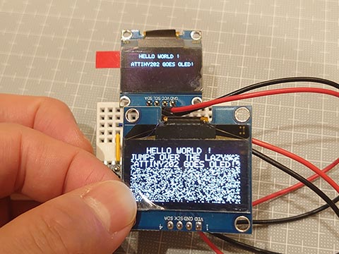
202duinoのピン配列をよくあるやつっぽく作ってみた。
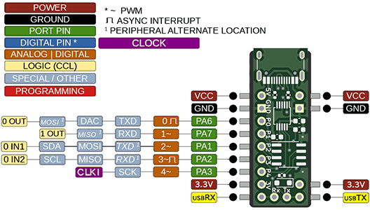

QUHSSHIK 0.96インチOLED I2C IIC 通信 128*64 OLEDモジュールデジタルディスプレイ回路基板自発光スペアパーツ, 白
- 出版社/メーカー: QUHSSHIK
- メディア:
UNO R4 とスピーカをつなぐシールドを作ってみた。 [Arduino]
DACで音声再生ができたものの、圧電サウンダの小さな音ではさみしい。
スピーカーでそこそこの音量での再生にチャレンジ。
使用したのは、10kΩの可変抵抗とNPNトランジスタと3.5mmジャック。
スピーカーは100円ショップで以前に購入したもの(アンプなし)。
回路図は以下のとおり。
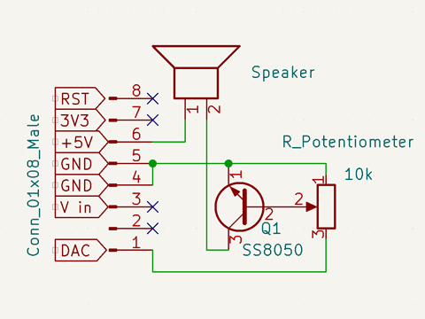
トランジスタのことよく分かっていない、データシート読めない私が作ったので間違っていると思うけど、ごめんなさい。でも動いた。
シールドはこんな感じ。
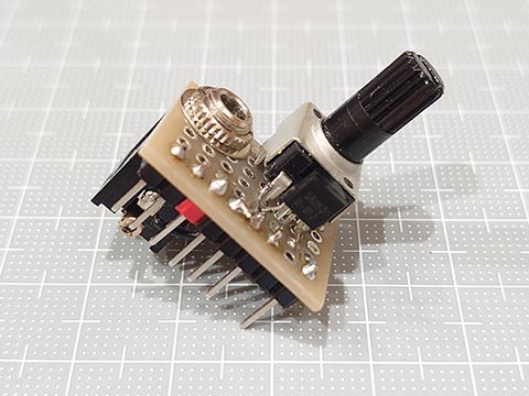
一列をさらに部分的にしか使っていないのでシールドと言っていいかも微妙ですが。
工夫した点は、UNO R4の平らな部分にジャックの底があたるようにすることで、高さ的にはピン+ピンソケットとほぼ同じ高さになりこころもち安定します。
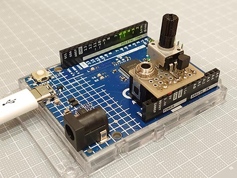
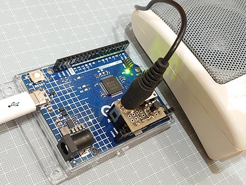
ボリュームを絞りすぎると音が出ず。開きすぎても音が出ず。
ちょうどいいところに持っていくと、まあまあ大きな音になります。
スピーカーでそこそこの音量での再生にチャレンジ。
使用したのは、10kΩの可変抵抗とNPNトランジスタと3.5mmジャック。
スピーカーは100円ショップで以前に購入したもの(アンプなし)。
回路図は以下のとおり。

トランジスタのことよく分かっていない、データシート読めない私が作ったので間違っていると思うけど、ごめんなさい。でも動いた。
シールドはこんな感じ。

一列をさらに部分的にしか使っていないのでシールドと言っていいかも微妙ですが。
工夫した点は、UNO R4の平らな部分にジャックの底があたるようにすることで、高さ的にはピン+ピンソケットとほぼ同じ高さになりこころもち安定します。


ボリュームを絞りすぎると音が出ず。開きすぎても音が出ず。
ちょうどいいところに持っていくと、まあまあ大きな音になります。
UNO R4 で WAVファイルを再生する [Arduino]
UNOでDACが使えることが分かったので、これを使って音声を再生してみました。
ファイル形式は、モノラル 8ビットのシンプルなwavファイルのみ。
<音源の準備>
・google翻訳の音声をmp3ファイルに変換してくれるサイトからゲット。
・これを Audacity を使って、モノラルの unsigned 8bit のwavファイルに変換。
・PROGMEM作蔵さん でC言語の配列に変換。(PROGMEMでなくてもいい)
バイナリファイルをC言語のデータ配列に変換する:放課後マイコンクラブ:SSブログ
https://hello-world.blog.ss-blog.jp/2016-10-16
スケッチは以下のとおりです。
レジスタ操作なしの純粋なArduinoスケッチで仕上げました。
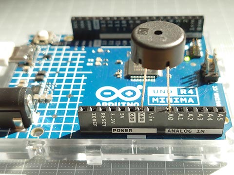
AVRと違いピンのドライブ能力が高くないようで、直接スピーカーをつなげてもうまく音がでませんでした。
圧電サウンダだとかなり小さい音ですが、きれいに聞こえました。
音声データはこんな感じ(略しています)
ファイル形式は、モノラル 8ビットのシンプルなwavファイルのみ。
<音源の準備>
・google翻訳の音声をmp3ファイルに変換してくれるサイトからゲット。
・これを Audacity を使って、モノラルの unsigned 8bit のwavファイルに変換。
・PROGMEM作蔵さん でC言語の配列に変換。(PROGMEMでなくてもいい)
バイナリファイルをC言語のデータ配列に変換する:放課後マイコンクラブ:SSブログ
https://hello-world.blog.ss-blog.jp/2016-10-16
スケッチは以下のとおりです。
レジスタ操作なしの純粋なArduinoスケッチで仕上げました。
AVRと違いピンのドライブ能力が高くないようで、直接スピーカーをつなげてもうまく音がでませんでした。
圧電サウンダだとかなり小さい音ですが、きれいに聞こえました。

#include "hw8k.h"                               // wave file data

void setup() {
  analogWriteResolution(8);
}

void loop() {
  playWav( hw8k_en );
  delay(500);
  playWav( hw8k_ja );
  delay(500);
}

void playWav( const uint8_t d[] ) {             // monoral 8bit only
  uint32_t i, rate, len, usInt, usExp;
  rate  = *(uint32_t*)(&d[ 0x18 ]);             // Sampling rate
  len   = *(uint32_t*)(&d[ 0x28 ]);             // Data size
  usInt = 1000000 / rate;                       // Time interval
  usExp = micros();
  for( i = 0x2c; i < len; i++ ) {
      analogWrite( DAC, d[ i ] );
      while( micros() - usExp < usInt );
      usExp = micros();
  }
}
音声データはこんな感じ(略しています)
const uint8_t hw8k_ja[] = {    // file size : 13100 bytes
  0x52,0x49,0x46,0x46,0x24,0x33,0x00,0x00,0x57,0x41,0x56,0x45,0x66,0x6d,0x74,0x20,
  0x10,0x00,0x00,0x00,0x01,0x00,0x01,0x00,0x40,0x1f,0x00,0x00,0x40,0x1f,0x00,0x00,
  0x01,0x00,0x08,0x00,0x64,0x61,0x74,0x61,0x00,0x33,0x00,0x00,0x80,0x7f,0x80,0x80,
  0x7f,0x80,0x7f,0x80,0x7f,0x80,0x7f,0x80,0x7f,0x80,0x7f,0x80,0x7f,0x80,0x7f,0x80,
        ......
  0x7f,0x80,0x80,0x7f,0x80,0x7f,0x80,0x7f,0x80,0x80,0x80,0x7f
};

const uint8_t hw8k_en[] = {    // file size : 10220 bytes
  0x52,0x49,0x46,0x46,0xe4,0x27,0x00,0x00,0x57,0x41,0x56,0x45,0x66,0x6d,0x74,0x20,
  0x10,0x00,0x00,0x00,0x01,0x00,0x01,0x00,0x40,0x1f,0x00,0x00,0x40,0x1f,0x00,0x00,
  0x01,0x00,0x08,0x00,0x64,0x61,0x74,0x61,0xc0,0x27,0x00,0x00,0x80,0x80,0x80,0x80,
  0x80,0x80,0x80,0x80,0x80,0x80,0x80,0x80,0x80,0x80,0x80,0x80,0x80,0x80,0x80,0x7f,
        ......
  0x7f,0x80,0x80,0x80,0x7f,0x80,0x7f,0x80,0x7f,0x80,0x7f,0x80
};
UNO R4 の DAC について調べてみた。 [Arduino]
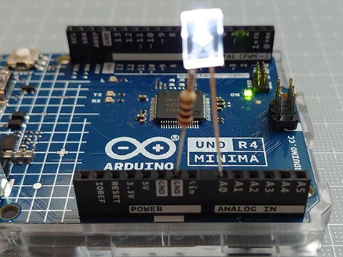
Arduino UNO R4 には、DAC (Digital Analog Converter) がついています。
アナログのA0ピンです。
デジタルでいうと14ピン。
UNO R4だと、定数で DAC および A0 が 14 となっていました。
どうやって出力するかというと、analogWrite を使うだけ。
analogWrite( ピン番号 , 値 );
でいい。
値は、
analogWriteResolution( 分解能(ビット数)) ;
で指定した範囲。
これを指定しない場合はデフォルトの8になるので、0-255の範囲。12を指定すると0-4095の範囲。
// UNO R4 DAC analogWrite

void setup() {
  analogWriteResolution( 12 );  // If not specified, the default is 8.
}

void loop() {
  static uint16_t val;
  val = ++val & 0x0fff;         // 0, 1, 2, ..., 4095 , 0, 1, 2, ...
  analogWrite( DAC, val );
  delayMicroseconds( 500 );
}
ピン番号がDAC対応ピン(DAC/A0/D14)だとDACで出力し、非対応ピンの場合にはPWMで出力するようになっています。13番ピン(LED_BUILTIN)にすると、PWMで内臓LEDが光ります。
DACピンでの analogWrite() は呼び出されると、大まかに以下の手順。
1. ピンがDAC使用可能ピンか確認
2. DACのチャンネル取得?
3. dac.cppのanalogWriteに値を渡す
4. 値を分解能に合わせてスケーリング
5. 値を書き込む
という手順です。
%localAppData%\Arduino15\packages\arduino\hardware\renesas_uno\1.0.4\cores\arduino
(1.0.4のところはバージョンによって異なります。)
ここの dac.cpp や analog.cpp を参照。
1, 2の作業を毎回ではなく、先にしておいて、3~5だけを行うのが以下のスケッチ。
少し早くなります。(delayMicroseconds()をなくすとよくわかります。)
// UNO R4 DAC analogWrite (faster)

#include <dac.h>

static CDac dac( A0 );

void setup() {
  analogWriteResolution( 12 );  // If not specified, the default is 8.
}

void loop() {
  static uint16_t val;
  val = ++val & 0x0fff;         // 12bit : 0, 1, 2, ..., 4095 , 0, 1, 2, ...
  dac.analogWrite( val );       // faster
  delayMicroseconds( 500 );
}
これでいいのかどうかはわからないけど、とりあえず動いている。
analogWrite()のかわりに、init()とset()だけでいけると思ったけど、だめだった。
さらに、レジスタをいじってみる。(5の作業のみ。)
// UNO R4 DAC analogWrite (fastest)

void setup() {
  analogWriteResolution( 12 );  // If not specified, the default is 8.
  analogWrite( DAC, 0 );        // For initialization.
}

void loop() {
  static uint16_t val;
  val = ++val & 0x0fff;         // 12bit : 0, 1, 2, ... , 4095, 0, 1, 2, ...
  R_DAC->DADR[0] = val;
  delayMicroseconds( 500 );
}
DACの初期設定もレジスタをいじるのは大変なので、analogWrite( DAC, 0 ); を1回呼び出すことで代用。
処理速度は断然速いです。
(delayMicroseconds()を外して書き込み、UNO R4を振ると残像の細かさがダントツです。)
(LEDの明るさで動作確認をしたけど、LEDは一定の電圧以下では光らないので、LEDの明るさ調整にはPWMのほうが向いていそう。)
CH552 で リモコン信号をシリアル送信 [Arduino]
CH552にも移植してみました。
Ch55xduinoで注意が必要なのは、、
・C++ではなくCである
・pulseIn()がない
・シリアル通信がいつものと異なる
pulseIn()については、100μ秒オーダー程度の精度で十分なので、micros()で自作。
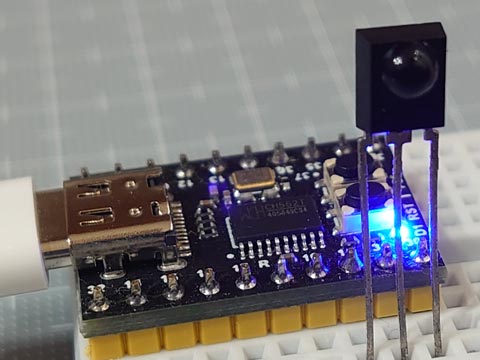
ちなみに、CH552 のピン P1.0~P1.7, P3.0~P3.7 のうち、CH552 mini coreでは、P1.2, P1.3 は外部クリスタル、P3.6, P3.7 はそれぞれUDP, UDMで、USBとつながっているためI/Oピンには使えません。
ちょっとこれで嵌りました。
Ch55xduinoで注意が必要なのは、、
・C++ではなくCである
・pulseIn()がない
・シリアル通信がいつものと異なる
pulseIn()については、100μ秒オーダー程度の精度で十分なので、micros()で自作。

// IR Receive and Decode (CH55x ver.)

#define IR_IN    11          // IR Receiver pin

uint32_t pulseIn(uint8_t pin, uint8_t state, uint32_t timeout) {
    uint32_t  usExp = micros();
    while( digitalRead( pin ) == state )  if( micros() - usExp > timeout ) return 0;
    while( digitalRead( pin ) != state )  if( micros() - usExp > timeout ) return 0;
    uint32_t  usOrg = micros();
    while( digitalRead( pin ) == state )  if( micros() - usExp > timeout ) return 0;
    return micros() - usOrg;
}

void setup() {
  pinMode( IR_IN , INPUT );                     // input  Vout(active low, negative logic)
  pinMode(  31 ,  OUTPUT ); digitalWrite( 31, LOW  );   // LOW  (*use as GND)
  pinMode(  30 ,  OUTPUT ); digitalWrite( 30, HIGH );   // HIGH (*use as Vcc)
}

void loop() {
  uint32_t  irData = 0;
  uint8_t   irProtocol = 0, irBit = 0;
  __xdata uint8_t   irArray[20] = {0};

  // ****** Receive and Decode IR signals ******
  uint16_t  us = pulseIn( IR_IN, LOW , 65535 ); // Judge the protocol by the length of the leader section (usec.)
  if      ( us > 2000 && us <  3000 ) {         //  *** SIRC ***
      irProtocol = 'S';                         //  T=600us, ON/OFF : leader= 4T/1T, 0=1T/1T, 1=2T/1T
      for(;(us = pulseIn( IR_IN, LOW , 3000 )); irBit++)
        if( us > 1000 && us <  1500 ) irData |= (1UL << irBit);
  }else if( us > 3500 && us <  5000 ) {         //  *** AEHA ***
      irProtocol = 'A';                         //  T=425us, ON/OFF : leader= 8T/4T, 0=1T/1T, 1=1T/3T, stop=1T
      while( digitalRead( IR_IN ) );
      for(;(us = pulseIn( IR_IN, HIGH, 4000 )); irBit++)
        if( us > 1050 && us <  1500 ) irArray[ irBit / 8 ] |= (1 << (irBit % 8) );
  }else if( us > 7200 && us < 11000 ) {         //  *** NEC ***
      irProtocol = 'N';                         //  T=560us, ON/OFF : leader=16T/8T, 0=1T/1T, 1=1T/3T, stop=1T
      while( digitalRead( IR_IN ) );
      for(;(us = pulseIn( IR_IN, HIGH, 3000 )); irBit++)
        if( us > 1350 && us <  2000 ) irData |= (1UL << irBit);
  }else return;

  // ****** Display results by protocol ******
  USBSerial_print( irProtocol == 'S' ? "SIRC: " : irProtocol == 'A' ? "AEHA: " : "NEC : " );
  if( !irBit ) {
    USBSerial_println( " (repeat code) " );
    return;
  }
  USBSerial_print( irBit );
  USBSerial_print( "bit" );
  if( irProtocol == 'A' ) {
    for( uint8_t i = 0; i < ( (irBit + 7) / 8 ); i++ ) {
      USBSerial_print((irArray[i] < 0x10) ? " 0x0" : " 0x" );
      USBSerial_print( irArray[i], HEX );
    }
  } else {
      USBSerial_print( " 0x" );
      USBSerial_print( irData, HEX );
      USBSerial_print( "\t0b" );
      USBSerial_print( irData, BIN );
  }
  USBSerial_println("");
}
ちなみに、CH552 のピン P1.0~P1.7, P3.0~P3.7 のうち、CH552 mini coreでは、P1.2, P1.3 は外部クリスタル、P3.6, P3.7 はそれぞれUDP, UDMで、USBとつながっているためI/Oピンには使えません。
ちょっとこれで嵌りました。
202duino で リモコン信号をシリアル送信 [Arduino]
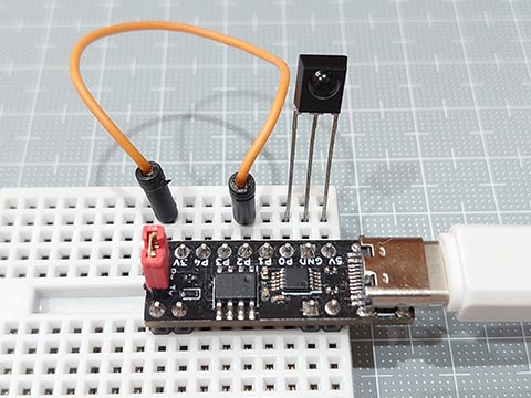
文字列と数値(n進法の整数)をシリアル出力する関数もつくって、自作シリアル送信プログラムを赤外線リモコン受信スケッチと組み合わせてみた。
赤外線リモコンの受信を簡単なスケッチで。:放課後マイコンクラブ:SSブログ
https://hello-world.blog.ss-blog.jp/2023-09-09
これと組み合わせて、、
余裕で2kBに収まりました。
赤外線リモコンの受信を簡単なスケッチで。:放課後マイコンクラブ:SSブログ
https://hello-world.blog.ss-blog.jp/2023-09-09
これと組み合わせて、、
最大2048バイトのフラッシュメモリのうち、スケッチが1576バイト(76%)を使っています。
最大128バイトのRAMのうち、グローバル変数が10バイト(7%)を使っていて、ローカル変数で118バイト使うことができます。
余裕で2kBに収まりました。

// IR Receive and Decode
#define IR_IN   0               // IR Receiver pin
#define TX      2               // Serial TX pin
#define BAUD    9600            // baud rate

void setup() {
  pinMode( TX   , OUTPUT );                     // Tx pin
  pinMode( IR_IN , INPUT );                     // input  Vout(active low, negative logic)
}

void loop() {
  uint32_t  irData = 0;
  uint8_t   irProtocol = 0, irBit = 0, irArray[20] = {0};

  // ****** Receive and Decode IR signals ******
  uint16_t  us = pulseIn( IR_IN, LOW , 65535 ); // Judge the protocol by the length of the leader section (usec.)
  if      ( us > 2000 && us <  3000 ) {         //  *** SIRC ***
      irProtocol = 'S';                         //  T=600us, ON/OFF : leader= 4T/1T, 0=1T/1T, 1=2T/1T
      for(;(us = pulseIn( IR_IN, LOW , 3000 )); irBit++)
        if( us > 1000 && us <  1500 ) irData |= (1UL << irBit);
  }else if( us > 3500 && us <  5000 ) {         //  *** AEHA ***
      irProtocol = 'A';                         //  T=425us, ON/OFF : leader= 8T/4T, 0=1T/1T, 1=1T/3T, stop=1T
      while( digitalRead( IR_IN ) );
      for(;(us = pulseIn( IR_IN, HIGH, 4000 )); irBit++)
        if( us > 1050 && us <  1500 ) irArray[ irBit / 8 ] |= (1 << (irBit % 8) );
  }else if( us > 7200 && us < 11000 ) {         //  *** NEC ***
      irProtocol = 'N';                         //  T=560us, ON/OFF : leader=16T/8T, 0=1T/1T, 1=1T/3T, stop=1T
      while( digitalRead( IR_IN ) );
      for(;(us = pulseIn( IR_IN, HIGH, 3000 )); irBit++)
        if( us > 1350 && us <  2000 ) irData |= (1UL << irBit);
  }else return;

  // ****** Display results by protocol ******
  serialPrintStr( irProtocol == 'S' ? "SIRC: " : irProtocol == 'A' ? "AEHA: " : "NEC : " );
  if( !irBit ) {
    serialPrintStr( " (repeat code) \n" );
    return;
  }
  serialPrintNum( irBit, DEC );
  serialPrintStr( "bit" );
  if( irProtocol == 'A' ) {
    for( uint8_t i = 0; i < ( (irBit + 7) / 8 ); i++ ) {
      serialPrintStr((irArray[i] < 0x10) ? " 0x0" : " 0x" );
      serialPrintNum( irArray[i], HEX );
    }
  } else {
      serialPrintStr( " 0x" );
      serialPrintNum( irData, HEX );
      serialPrintStr( "\t0b" );
      serialPrintNum( irData, BIN );
  }
  serialPrintStr("\n");
}

void inoTX( uint8_t c ) {       // *** OK up to 19200bps at 20MHz(ATtiny202) ***
    digitalWrite( TX,  LOW );                   // start bit
    delayMicroseconds( 1000000 / BAUD );
    for(uint8_t i = 0; i < 8; i++ ) {           // data bits
        digitalWrite( TX, ( c >> i ) & 1 );
        delayMicroseconds( 1000000 / BAUD );
    }
    digitalWrite( TX, HIGH );                   // stop bit
    delayMicroseconds( 1000000 / BAUD );
}

void serialPrintStr( const char *str ) {
    for( ; str[0]; str++ )  inoTX( str[0] );
}

void serialPrintNum( uint32_t num , uint8_t N ) {
    uint8_t n[32], dig = 0;
    do { n[dig++] = num % N; }  while( num /= N );
    for( ; dig; ) inoTX( "0123456789ABCDEF"[ n[--dig] ] );
}

// Uses less RAM, but requires more flash memory and calculations
void serialPrintNum2( uint32_t num , uint8_t N ) {
    uint32_t  t  = num, pwr  = 1;
    for(    ; t /= N  ; pwr *= N );
    for(    ; pwr     ; pwr /= N ) inoTX( "0123456789ABCDEF"[ (num / pwr) % N ] );
}


