Arduino1.0 で ATtiny2313 を動かす [Arduino]
次のページで Arduino1.0 で ATitiny 44/45/84/85 のプログラムをしています。
High-Low Tech - Programming an ATtiny w/ Arduino 1.0
http://hlt.media.mit.edu/?p=1695
これを参考に見よう見まねで ATtiny2313 用の「board.txt」と「pins_arduino.h」を作ってみました。
とりあえず動いただけです。
あまり詳しいことは分からずやっています。
参考程度で、、。
間違っていたらごめんなさいです。
「board.txt」 に次の設定を追加
続いて、
「variants」フォルダの中に「tn2313」フォルダを作り、その中に、「pins_arduino.h」というファイルを作ります。
下記のとおりです。
(フォルダ名を tiny8, tiny14 のように足の数にしなかったのは、同じ20本の足でも ATtiny861のように配列が全然ちがうタイプがあったためです。)
「pins_arduino.h」
これだけです。
「Tools」 → 「Burn Bootloader」 で Fuse の設定もできました。
ATtiny45 などで苦労した ArduinoISP の問題も発生していません。(Uno(R1), 1.0, Windows で確認)
analogWrite の確認のためのスケッチ
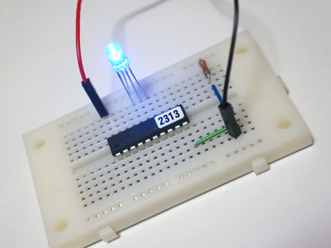
虹色です。
High-Low Tech - Programming an ATtiny w/ Arduino 1.0
http://hlt.media.mit.edu/?p=1695
これを参考に見よう見まねで ATtiny2313 用の「board.txt」と「pins_arduino.h」を作ってみました。
とりあえず動いただけです。
あまり詳しいことは分からずやっています。
参考程度で、、。
間違っていたらごめんなさいです。
「board.txt」 に次の設定を追加
############################################

attiny2313-8.name=ATtiny2313 (internal 8 MHz clock)
attiny2313-8.bootloader.low_fuses=0xE4
attiny2313-8.bootloader.high_fuses=0xDF
attiny2313-8.bootloader.extended_fuses=0xff
attiny2313-8.upload.maximum_size=2048
attiny2313-8.build.mcu=attiny2313
attiny2313-8.build.f_cpu=8000000L
attiny2313-8.build.core=arduino:arduino
attiny2313-8.build.variant=tn2313

############################################
続いて、
「variants」フォルダの中に「tn2313」フォルダを作り、その中に、「pins_arduino.h」というファイルを作ります。
下記のとおりです。
(フォルダ名を tiny8, tiny14 のように足の数にしなかったのは、同じ20本の足でも ATtiny861のように配列が全然ちがうタイプがあったためです。)
「pins_arduino.h」
/*
  pins_arduino.h - Pin definition functions for Arduino
  Part of Arduino - http://www.arduino.cc/

  Copyright (c) 2007 David A. Mellis

  This library is free software; you can redistribute it and/or
  modify it under the terms of the GNU Lesser General Public
  License as published by the Free Software Foundation; either
  version 2.1 of the License, or (at your option) any later version.

  This library is distributed in the hope that it will be useful,
  but WITHOUT ANY WARRANTY; without even the implied warranty of
  MERCHANTABILITY or FITNESS FOR A PARTICULAR PURPOSE.  See the GNU
  Lesser General Public License for more details.

  You should have received a copy of the GNU Lesser General
  Public License along with this library; if not, write to the
  Free Software Foundation, Inc., 59 Temple Place, Suite 330,
  Boston, MA  02111-1307  USA

  $Id: wiring.h 249 2007-02-03 16:52:51Z mellis $

  Modified 22-02-2012 for attiny2313
*/

#ifndef Pins_Arduino_h
#define Pins_Arduino_h

#include <avr/pgmspace.h>

// On the Arduino board, digital pins are also used
// for the analog output (software PWM).  Analog input
// pins are a separate set.

// ATMEL ATTINY2313
//
//                  +-\/-+
//            PA2  1|    |29  VCC
// RX   (D 0) PD0  2|    |19  PB7 (D 16)
// TX   (D 1) PD1  3|    |18  PB6 (D 15)
//      (D 2) PA1  4|    |17  PB5 (D 14)
//      (D 3) PA0  5|    |16  PB4 (D 13)*
// INT0 (D 4) PD2  6|    |15  PB3 (D 12)*
// INT1 (D 5) PD3  7|    |14  PB2 (D 11)*
//      (D 6) PD4  8|    |13  PB1 (D 10)
//     *(D 7) PD5  9|    |12  PB0 (D 9)
//            GND 10|    |11  PD6 (D 8)
//                  +----+
//
// * indicates PWM port

#define NUM_DIGITAL_PINS            17
#define NUM_ANALOG_INPUTS           0
#define analogInputToDigitalPin(p)  (-1)
#define digitalPinHasPWM(p)         ((p) == 7 || (p) == 11 || (p) == 12 || (p) == 13 )

const static uint8_t MOSI = 14;
const static uint8_t MISO = 15;
const static uint8_t SCK  = 16;

const static uint8_t SDA = 14;
const static uint8_t SCL = 16;

#define digitalPinToPCICR(p)    ( ((p) >= 9 && (p) <= 16) ? (&GIMSK)  : ((uint8_t *)0) )
#define digitalPinToPCICRbit(p) ( ((p) >= 9 && (p) <= 16) ? (PCIE)    : ((uint8_t *)0) )
#define digitalPinToPCMSK(p)    ( ((p) >= 9 && (p) <= 16) ? (&PCMSK)  : ((uint8_t *)0) )
#define digitalPinToPCMSKbit(p) ( ((p) >= 9 && (p) <= 16) ? ((p) - 9) : ((uint8_t *)0) )

#ifdef ARDUINO_MAIN

const uint16_t PROGMEM port_to_mode_PGM[] = {
	NOT_A_PORT,
	(uint16_t)&DDRA,
	(uint16_t)&DDRB,
	NOT_A_PORT,
	(uint16_t)&DDRD,
};

const uint16_t PROGMEM port_to_output_PGM[] = {
	NOT_A_PORT,
	(uint16_t)&PORTA,
	(uint16_t)&PORTB,
	NOT_A_PORT,
	(uint16_t)&PORTD,
};

const uint16_t PROGMEM port_to_input_PGM[] = {
	NOT_A_PORT,
	(uint16_t)&PINA,
	(uint16_t)&PINB,
	NOT_A_PORT,
	(uint16_t)&PIND,
};

const uint8_t PROGMEM digital_pin_to_port_PGM[] = {
	PD, /* 0 */
	PD,
	PA,
	PA,
	PD,
	PD,
	PD,
	PD,
	PD, /* 8 */
	PB,
	PB,
	PB,
	PB,
	PB,
	PB, /* 14 */
	PB,
	PB,
};

const uint8_t PROGMEM digital_pin_to_bit_mask_PGM[] = {
	_BV(0), /* 0 */
	_BV(1),
	_BV(1),
	_BV(0),
	_BV(2),
	_BV(3),
	_BV(4),
	_BV(5),
	_BV(6), /* 8 */
	_BV(0),
	_BV(1),
	_BV(2),
	_BV(3),
	_BV(4),
	_BV(5), /* 14 */
	_BV(6),
	_BV(7),
};

const uint8_t PROGMEM digital_pin_to_timer_PGM[] = {
	NOT_ON_TIMER,
	NOT_ON_TIMER,
	NOT_ON_TIMER,
	NOT_ON_TIMER,
	NOT_ON_TIMER,
	NOT_ON_TIMER,
	NOT_ON_TIMER,
	TIMER0B,
	NOT_ON_TIMER,
	NOT_ON_TIMER,
	NOT_ON_TIMER,
	TIMER0A,
	TIMER1A,
	TIMER1B,
	NOT_ON_TIMER,
	NOT_ON_TIMER,
	NOT_ON_TIMER,
};

#endif

#endif
これだけです。
「Tools」 → 「Burn Bootloader」 で Fuse の設定もできました。
ATtiny45 などで苦労した ArduinoISP の問題も発生していません。(Uno(R1), 1.0, Windows で確認)
analogWrite の確認のためのスケッチ
// Full Color LED で 虹色イルミネーション
#define GET_RAINBOW(TONE) (((TONE)<256) ? (TONE):((TONE)<768) ? 255:(((TONE)<1024) ? (1023-(TONE)):0))

void setup() {
  pinMode( 11, OUTPUT );
  pinMode( 12, OUTPUT );
  pinMode( 13, OUTPUT );
}

void loop() {
  for(unsigned int t = 0; t < 1536; t++ ) {
    analogWrite( 11, GET_RAINBOW(   t                 ) );
    analogWrite( 12, GET_RAINBOW( ( t +  512 ) % 1536 ) );
    analogWrite( 13, GET_RAINBOW( ( t + 1024 ) % 1536 ) );
    delay( 5 );
  }
}
虹色です。
タグ:ATtiny2313


